Intelligent Control System of Asphalt Foaming Machine

A control system and a foaming machine technology, applied in the field of asphalt foaming, can solve problems such as the inability to intuitively reflect the amount of asphalt and the amount of water added, the quality accident and quality loss of asphalt roads, and the inability to effectively ensure the quality of asphalt foaming. Eliminate hidden quality risks, reduce hidden quality risks, and ensure the effect of heating temperature

Active Publication Date: 2018-07-03
YICHANG JIANGXIA MARINE MACHINERY
View PDF7 Cites 0 Cited by
  • Summary
  • Abstract
  • Description
  • Claims
  • Application Information

AI Technical Summary

Problems solved by technology

At present, the water addition control of the asphalt foaming machine is controlled by the water pressure feedback. Since the water pressure is affected by the complex pressure changes on the side of the asphalt flow pipe, it cannot directly reflect the amount of asphalt and the amount of water added, making it difficult to mix asphalt and water. control
This method is extensively controlled and cannot effectively guarantee the quality of asphalt foaming. There are quality hidden dangers, which may lead to major quality accidents and quality losses in asphalt road construction.
[0003] Chinese patent document CN 101739000 B discloses an intelligent control system for an asphalt foaming device. It proposes to use sensors, mainly flow meters, to intelligently control the foaming of asphalt. The comparison method, and introduce more control parameters, such as foaming water flow, mixing water flow and air flow, and set up an automatic temperature control function, the temperature signal is collected by the temperature transmitter and sent to the control module, the control module Control the heating element on the asphalt pipeline for heating; the existing problem is that the control system involves too many parameters, the control is difficult, and the system is prone to collapse in the actual production process

Method used


Image

  • Intelligent Control System of Asphalt Foaming Machine
  • Intelligent Control System of Asphalt Foaming Machine
  • Intelligent Control System of Asphalt Foaming Machine

Examples


Embodiment Construction

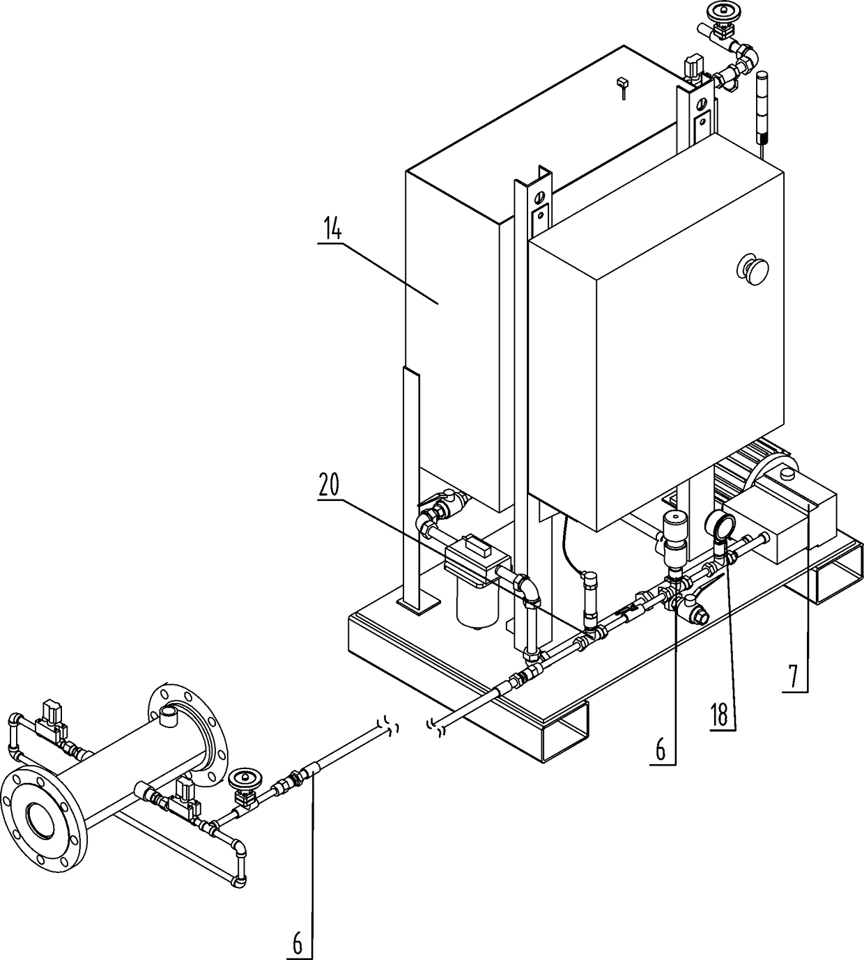
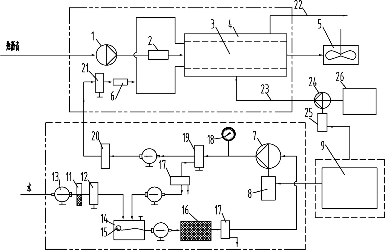
[0026] like Figure 1~3 Among them, an intelligent control system for an asphalt foaming machine, the output port of the asphalt pump 1 is connected to the inlet of the foaming pipe 3, and an asphalt flow sensor 2 is arranged between the output port of the asphalt pump 1 and the foaming pipe 3; The asphalt flow sensor 2 in the example adopts a dynamic difference target flowmeter, and the accuracy error is ±0.1%~0.2%.

[0027] The outer wall of foam pipe 3 is provided with jacket 4, and jacket 4 is connected with oil inlet pipe 23 and oil discharge pipe 22; In the constant heat furnace 26, heating oil at a constant temperature is output in circulation.

[0028] The output port of the water pump 7 is connected to the water inlet of the foam pipe 3, and a water flow sensor 6 is arranged between the output port of the water pump 7 and the foam pipe 3;

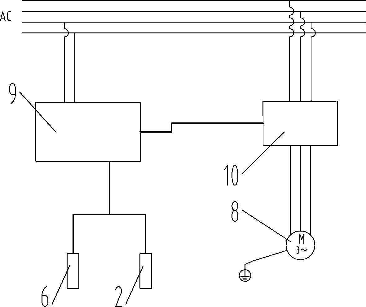
[0029] The water flow sensor 6 and the asphalt flow sensor 2 are connected to the control device 9 , the control device 9 is co...


PUM


Abstract

The invention provides an intelligent control system for an asphalt foaming machine. The output port of the asphalt pump is connected to the inlet of the foaming pipe, and an asphalt flow sensor is arranged between the output port of the asphalt pump and the foaming pipe; the outer wall of the foaming pipe A jacket is provided, and the jacket is connected with the oil inlet pipe and the oil discharge pipe; the output port of the water pump is connected with the water inlet of the foaming pipe, and a water flow sensor is arranged between the output port of the water pump and the foaming pipe; the water flow sensor and the asphalt flow rate The sensor is connected with the control device, the control device is connected with the frequency converter, and the frequency converter is connected with the motor driving the water pump. By setting the asphalt flow sensor and the water flow sensor, the water flow is adjusted with the data of the asphalt flow sensor as a reference, so as to realize the precise control of the ratio of water and asphalt. Guarantee the quality of asphalt foaming and eliminate quality hazards.

Description

technical field [0001] The invention relates to the field of asphalt foaming, in particular to an intelligent control system for an asphalt foaming machine. Background technique [0002] Asphalt foaming and warm mixing technology, because of its advantages of energy saving, emission reduction, green environmental protection, etc., has been widely concerned by the road industry at home and abroad. At present, the water addition control of the asphalt foaming machine is controlled by the water pressure feedback. Since the water pressure is affected by the complex pressure changes on the side of the asphalt flow pipe, it cannot directly reflect the amount of asphalt and the amount of water added, making it difficult to mix asphalt and water. control. This method is extensively controlled, cannot effectively guarantee the quality of asphalt foaming, and has quality hidden dangers, which may lead to major quality accidents and quality losses in asphalt road construction. [000...

Claims


Application Information

Patent Timeline
Patent Type & Authority Patents(China)
IPC IPC(8): G05D27/02E01C19/02
CPCE01C19/02G05D27/02
Inventor 何明黄恋王军黑保江
Owner YICHANG JIANGXIA MARINE MACHINERY
Why Eureka
Try Eureka