
Voltage doubler rectifier circuit circuit entity system

A voltage-doubling rectifier circuit and circuit technology, applied in printed circuits, printed circuits, printed circuits connected with non-printed electrical components, etc., can solve the problems of limited insulation capacity, poor electrical performance, and high cost, and achieve space occupation The effect of shrinking, improving work reliability, and improving withstand voltage performance

Active Publication Date: 2018-07-31
白成东
View PDF6 Cites 0 Cited by
  • Summary
  • Abstract
  • Description
  • Claims
  • Application Information

AI Technical Summary

Problems solved by technology

The existing voltage doubler rectifier circuit board design has technical problems such as poor electrical performance, especially unsatisfactory withstand voltage performance, specifically including: there is a step-up gradient potential difference between the two pins of the capacitor and between adjacent capacitors. It is possible to increase the spacing between the capacitor pins and the pads between adjacent capacitors to improve the withstand voltage performance, but due to the limitation of the size of the circuit board, the limitation of increasing the spacing is very large. Insulating boards such as wood boards, glass fiber boards or plastic boards, but due to the limited insulation capacity of circuit board materials, if there are various adverse factors that affect the insulation performance due to the surrounding environment, it will increase the probability of capacitors and capacitors. Discharge breakdown, these situations happen from time to time, resulting in unsatisfactory voltage resistance and low working reliability of the solid circuit board products of the voltage doubler circuit. The technical research and development personnel are more trying to start with the circuit principle design, hoping to solve it. However, the effect is limited, and the means are complicated and the cost is abnormally high
Existing circuit products can only be expanded horizontally on the circuit board surface to provide a larger pad setting board surface for increasing the number of voltage doubling stages. Each additional level of voltage doubling circuit will lead to a large overall space occupation of the circuit board ; Moreover, the existing voltage doubler rectifier circuit board is also difficult to install and set the shimming ring, which is another main technical reason affecting the reliability performance

Method used


Image

  • Voltage doubler rectifier circuit circuit entity system
  • Voltage doubler rectifier circuit circuit entity system
  • Voltage doubler rectifier circuit circuit entity system

Examples


Embodiment Construction

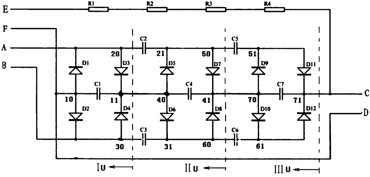
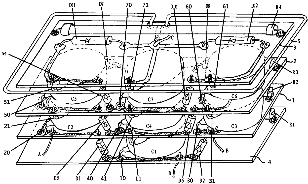
[0008] by figure 1 The shown triple full-wave voltage doubling rectifier circuit is taken as an example, and the technical content of the voltage doubling rectifier circuit circuit entity system of the application of the present invention is described in detail. The triple voltage steps of the triple voltage full-wave rectifier circuit in this embodiment are respectively arranged on each voltage doubler step circuit board according to the gradient level, and each voltage doubler step is respectively arranged on each layer of the vertical spacing distribution according to the voltage doubler sequence On the voltage doubling step circuit boards 1, 2, and 3, in each voltage doubling step, for example, the two pins 10 and 11 of the capacitor C1 of the first voltage doubling step IU are welded to the substrate 4 and the upper voltage doubling step circuit board 1 respectively Above, the two pins 20 and 21, 30 and 31, 40 and 41 of each capacitor of the capacitors C2, C3, and C4 of ...


PUM


Abstract

The invention provides a voltage doubling rectifying circuit entity system. Two pins of a capacitor in each voltage doubling stage are welded to a last voltage doubling stage circuit board bonding pad and a next voltage doubling stage circuit board bonding pad in the homopolar direction respectively, series-connecting node lapping circuit boards of capacitors of every two adjacent voltage doubling stages serve as voltage doubling stage circuit boards, and each voltage doubling stage circuit board is provided with a rectifier diode matched with the capacitor of the corresponding stage. According to the voltage doubling rectifying circuit entity system, the voltage resistance of a voltage doubling rectifying circuit board product is improved, and the space occupying size is greatly reduced.

Description

technical field [0001] The application of the present invention relates to the engineering design of a physical circuit board of a functional circuit, in particular to the engineering design of a physical circuit board of a voltage doubler rectifier circuit and a high voltage doubler rectifier circuit. Background technique [0002] The voltage doubler rectifier circuit is a high-voltage, low-current boost function circuit composed of rectifier diodes and withstand voltage capacitors. The basic components of this functional circuit include rectifier diodes and capacitors, and a current-limiting resistor voltage detection circuit is also configured. Arranged on a circuit board by welding from input to output according to the voltage doubling level sequence, such as figure 2 shown. The existing voltage doubler rectifier circuit board design has technical problems such as poor electrical performance, especially unsatisfactory withstand voltage performance, specifically includin...

Claims


Application Information

Patent Timeline
Patent Type & Authority Patents(China)
IPC IPC(8): H02M3/28H05K1/18
CPCH05K1/182H05K2201/10015H05K2201/10174
Inventor 白成东孙坤王丹
Owner 白成东
Learn More