Numerical control punching and cutting integrated machine and alignment method thereof
An all-in-one machine and parameter technology, which is applied in the direction of boring/drilling, automatic control devices, drilling/drilling equipment, etc. Irregularly distributed processing holes and other problems, to achieve the effect of simple and reasonable mechanical structure, fast speed and wide application range
- Summary
- Abstract
- Description
- Claims
- Application Information
AI Technical Summary
Problems solved by technology
Method used
Image
Examples
Embodiment 1
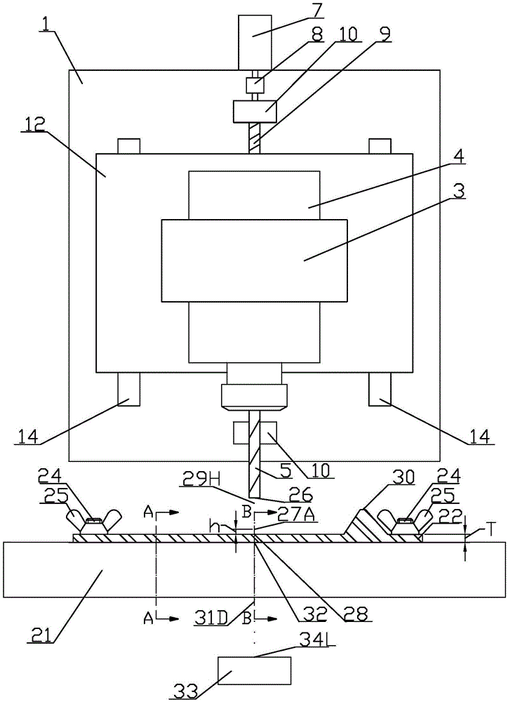
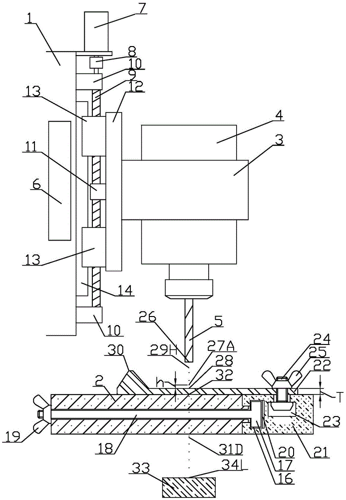
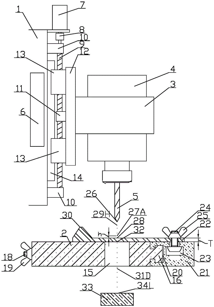
[0040]A CNC punching and cutting integrated machine, which consists of: a frame 1, a workbench 2, a spindle clamp 3, a spindle 4, and a machining tool 5, the controller 6 is installed on the frame 1, and the control The device 6 includes a display, a keyboard and a control box. The output shaft of the feed motor 7 is connected to the screw 9 through a coupling 8, and the screw 9 is connected to the frame 1 through a bearing bracket 10. The screw mandrel 9 is connected with a screw nut 11, the screw nut 11 is connected with a sliding table support plate 12, the top and bottom of the screw nut 11 are respectively connected with sliders 13, and the slider 13 is Slide on the guide rail 14, the guide rail 14 is connected to the front surface of the frame 1, the main shaft clamp 3 is connected to the slide table supporting plate 12, and the main shaft 4 is arranged on the main shaft clamp 3, The main shaft 4 is connected with a machining tool 5, the workbench 2 is fixed on the frame...
Embodiment 2
[0044] The alignment method of the CNC punching and cutting integrated machine described in Embodiment 1, which includes connecting the controller 6 to the frame 1, loading the CNC feed system into the controller 6 and inputting instructions through the keyboard , parameters and selection menu options are used to control the position of the tool nose 26 of the machining tool 5, and the coordinates of this position are called tool coordinates; the workbench 2 and the horizontal slide table 21 place the workpiece 22 together, after determining the workpiece coordinate system and the tool setting operation , also includes the following steps:
[0045] Step S101: start processing, this step is a preparation step for processing;
[0046] The preparation steps include drawing the processing line of the workpiece 22, marking the processing points, starting the machine, and setting the tool. If the workpiece 22 itself has information such as processing lines and processing points, the...
Embodiment 3
[0077] The alignment method of the CNC punching and cutting machine described in Embodiment 2 establishes the object coordinate system.
[0078] Step S201: preparing for tool setting;
[0079] The preparations for tool setting include starting the machine, finding a suitable tool, placing the position of the tool setting block 33, drawing up the zero point of the workpiece coordinate system, and calculating the tool setting parameter L, which do not involve the CNC feed system. There is a tool setting point 34 in the tool setting block 33, and the user calculates the vertical distance from the tool setting point 34 to the zero point 32 of the workpiece coordinate system designated by the user to set the value of the tool setting parameter L; according to the zero point 32 of the workpiece coordinate system and the tool setting point 34 The position relationship determines the sign of the tool setting parameter L. If the zero point 32 of the workpiece coordinate system is highe...
PUM
 Abstract
Description
Claims
Application Information
 - R&D
- Intellectual Property
- Life Sciences
- Materials
- Tech Scout
- Unparalleled Data Quality
- Higher Quality Content
- 60% Fewer Hallucinations
Browse by: Latest US Patents, China's latest patents, Technical Efficacy Thesaurus, Application Domain, Technology Topic, Popular Technical Reports.
© 2025 PatSnap. All rights reserved.Legal|Privacy policy|Modern Slavery Act Transparency Statement|Sitemap|About US| Contact US: help@patsnap.com


