Positioning machining method for thin hook-face parts

A curved surface part and processing method technology, applied in the field of part processing, can solve the problems of high processing cost, unsuitable for batch processing, low processing efficiency, etc., achieve high accuracy of repeated clamping and positioning, easy to master processing strategies, and improve processing efficiency Effect

Active Publication Date: 2016-04-27
ZHEJIANG XIZI AVIATION IND
View PDF4 Cites 9 Cited by
  • Summary
  • Abstract
  • Description
  • Claims
  • Application Information

AI Technical Summary

Problems solved by technology

[0006] (1) The processing time of the parts is long and the accuracy is poor. For the fuzzy parts of the aviation positioning reference, the processing strategy of first roughing and then finishing, subdividing the processing layer, and medium-speed and slow-feeding is adopted. The phenomenon of tool vibration caused by the continuous weakening of rigidity, and the processing efficiency is low, and the surface quality of the parts is poor; when using special tooling, the position accuracy of the parts is affected by the accuracy of the tooling itself and the correctness of the operator's clamping, and the quality is difficult to stabilize
[0007] (2) The process is cumbersome. Because there is no usable positioning reference for the part itself, when using a three-axis CNC machine tool for machining, it is impossible to achieve fast clamping and positioning for multi-face machining. It is necessary to repeatedly adjust the position for disassembly and assembly, and the clamping time is long. The workload is heavy, and the clamping speed and accuracy are affected by the operator's own skill level and experience, so it is impossible to accurately measure the man-hours of parts processing
[0008] (3) The process of process design and programming is complicated. Because the parts themselves have no usable positioning reference, when three-axis CNC machine tools are used for machining, the process programmers need to design the process bosses and mountings used for turning the parts according to the actual situation of the parts. In the clamping area, it is also necessary to design the reference transfer form according to the actual situation of the part and the actual operating ability of the operator. When the design of the part changes, or when similar parts appear, the above work also needs to be done again, which increases the number of such parts. Difficulty in crafting and programming, time-consuming and labor-intensive
[0009] (4) The processing of such parts usually requires the production of special fixtures or the use of four-axis and five-axis CNC machine tools. The processing cost is high and it is not suitable for batch processing
[0010] (5) Aeronautical materials are expensive, and the materials for clamping are seriously wasted
[0011] (6) The versatility of the fixture is not strong, and the tooling needs to be remanufactured after the specification and size of the parts change, the cost of the tooling is high, and the preparation period is long

Method used


Image

  • Positioning machining method for thin hook-face parts
  • Positioning machining method for thin hook-face parts
  • Positioning machining method for thin hook-face parts

Examples


Embodiment Construction

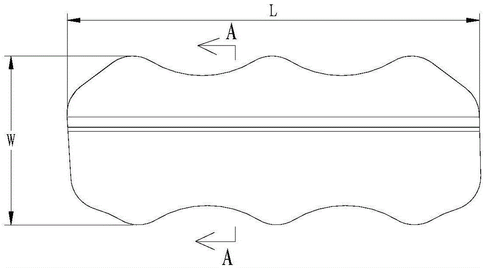
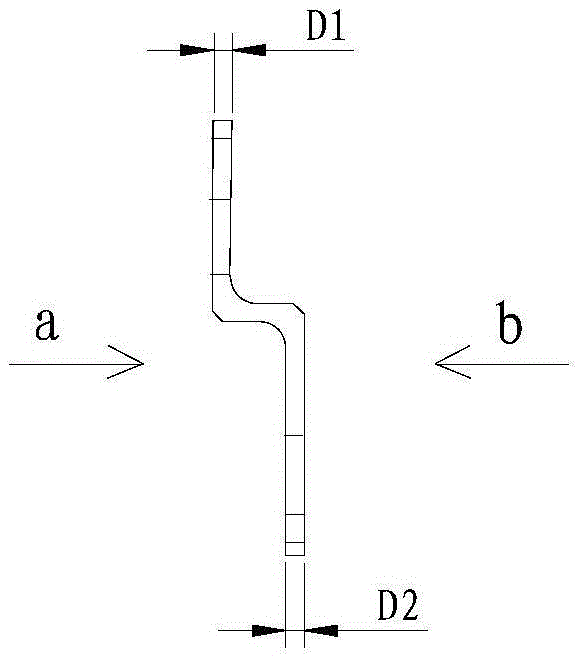
[0046] as Figure 1a , Figure 1b The thin curved surface part shown is taken as an example, and the positioning processing method of the thin curved surface part according to the present invention is described in detail.

[0047] like Figure 1a As shown, the length L of the thin curved surface part is 160mm, and the width W is 80mm, such as Figure 1b As shown, the thickness D1 and D2 of the thin curved surface part are both 2mm, and the front and back sides of the thin curved surface part ( Figure 1b The planes indicated by arrows a and b in the middle) are both curved surfaces.

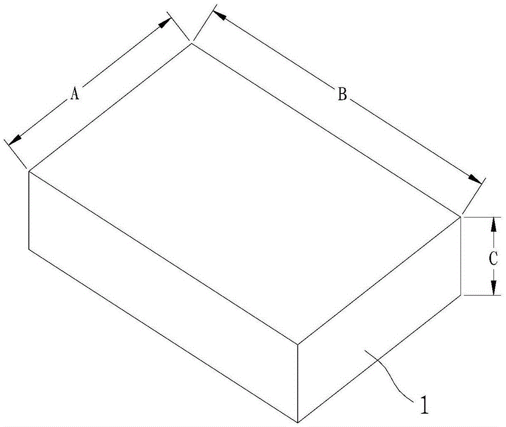
[0048]The positioning fixture of the three-axis CNC machine tool used in this embodiment is as follows image 3 As shown, the pneumatic clamping method is adopted, the main body is a pneumatic rectangular positioning seat, and the origin of the machining coordinate system XYZ of the part coincides with the rotation center of the positioning fixture 2 (that is, the origin of the machining coordi...


PUM

PropertyMeasurementUnit
thicknessaaaaaaaaaa
lengthaaaaaaaaaa
widthaaaaaaaaaa

Abstract

The invention discloses a positioning machining method for thin hook-face parts. The positioning machining method includes the specific machining processes that (1) the outline of a cutting part is machined; (2) the manner that one-time cutter feeding is carried out in the stock thickness direction and gradual cutter feeding is carried out in the stock width direction is used for machining the front face of the cutting part; (3) the front face of a transition part is cut to be thin; (4) a U-shaped chuck is turned over by 180 degrees around a rotation shaft of a positioning clamp, and the back face of the cutting part is machined in the cutter feeding manner adopted in the step (2); (5) the back face of the transition part is cut to be thin until only connecting lugs are left on the transition part; and (6) the connecting lugs are cut off to obtain the machined and molded thin hook-face parts. According to the positioning machining method, it is guaranteed that in the part machining process, the self rigidity keeps in the best state all the time, and vibration generated in the machining process is avoided.

Description

technical field [0001] The invention relates to the technical field of parts processing, in particular to a method for positioning and processing thin curved surface parts. Background technique [0002] In the field of aviation manufacturing, a large number of aluminum alloy parts such as joints and supports are designed with curved surfaces. The overall shape of the parts has many curved surfaces, and there is no plane. processing strategy. [0003] The processing process generally adopts the method of processing the front and back of the part separately. When processing the front, in addition to completely processing the shape of one side of the part, the method of reference transfer is also used to select a position on the blank to process the other side for positioning. benchmark. [0004] The processing strategy usually adopts the processing strategy of first roughing and then finishing, subdivision layer, reciprocating finishing, and slow cutting tool. The choice of...

Claims


Application Information

Patent Timeline
Patent Type & Authority Applications(China)
IPC IPC(8): B23P13/02
CPCB23P13/02
Inventor 梁峰陈志新李旭龙
Owner ZHEJIANG XIZI AVIATION IND
Why Eureka
Try Eureka