Gas mixing device of burner

A burner and aeration technology, applied in the burner, combustion method, combustion type, etc., can solve the problems of damage to the burner fan, uneven distribution of air volume, restricting the use of the burner, etc., to avoid damage to the fan and aeration effect. Excellent, promoting uniform distribution effect

Inactive Publication Date: 2016-04-27
HUNAN HUITONG ADVANCED MATERIALS
View PDF9 Cites 2 Cited by
  • Summary
  • Abstract
  • Description
  • Claims
  • Application Information

AI Technical Summary

Problems solved by technology

After the boiler is transformed into a gun-type burner with a metal fiber surface combustion method, in order to achieve uniform gas mixing, it is required that the length of the non-combustion gas-mixing area of ​​the burner should be long enough during the design process of the burner, and the occupied area should be correspondingly large. , but the actual situation is that the existing residential areas, hotels and other public places can provide limited installation space, which greatly limits the use of this type of burner
And now there are many traditional gun burners that need to be transformed into burners with metal fiber burners, but the opening of the boiler to connect to the burner is generally only a little larger than the flame tube of the original burner. According to the usual metal fiber surface Combustion transformation methods require enlarging the opening to install the modified ignition and flame detection and other supporting devices, and the distance between the gas mixing chamber of the existing burner is relatively long, and the transformation is relatively difficult, and in case of tempering, it cannot Timely pressure relief may cause damage to the burner fan and cause safety accidents
[0004] In addition, due to the centrifugal fans used in traditional gun-type burners, the distribution of air volume in the circumferential direction of the flame cylinder (burner head) is very uneven. In particular, different brands of burners have differences in air duct design. The unevenness of the gas is also very different, especially in the case of short-distance gas mixing, the usual transformation methods are difficult to solve this problem

Method used


Image

  • Gas mixing device of burner
  • Gas mixing device of burner
  • Gas mixing device of burner

Examples


Embodiment 1

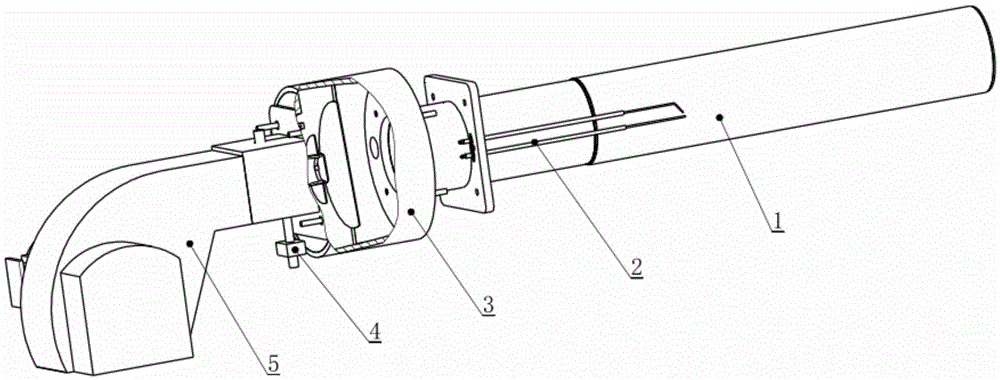
[0041] see figure 1 , the burner in the illustration includes a metal fiber furnace head 1, an ignition needle assembly 2, a gas mixing chamber 3, a gas inlet joint 4, a burner fan 5, etc. The burner in this embodiment is a gun-type burner, and its Burner burner burner 1 adopts metal fiber burner. The metal fiber burner head 1 of the burner is connected to the gas outlet of the gas mixing chamber 3 through a flange connection, the gas inlet joint 4 is connected to the gas outlet assembly in the gas mixing chamber 3, and the ignition needle assembly 2 is fixed on the burner burner head. On the surface of the metal fiber mesh, the air inlet of the gas mixing chamber 3 is connected with the air outlet of the burner fan 5 .

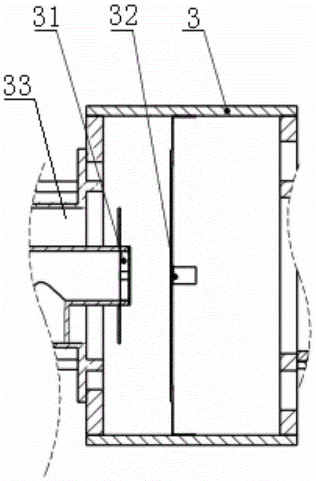
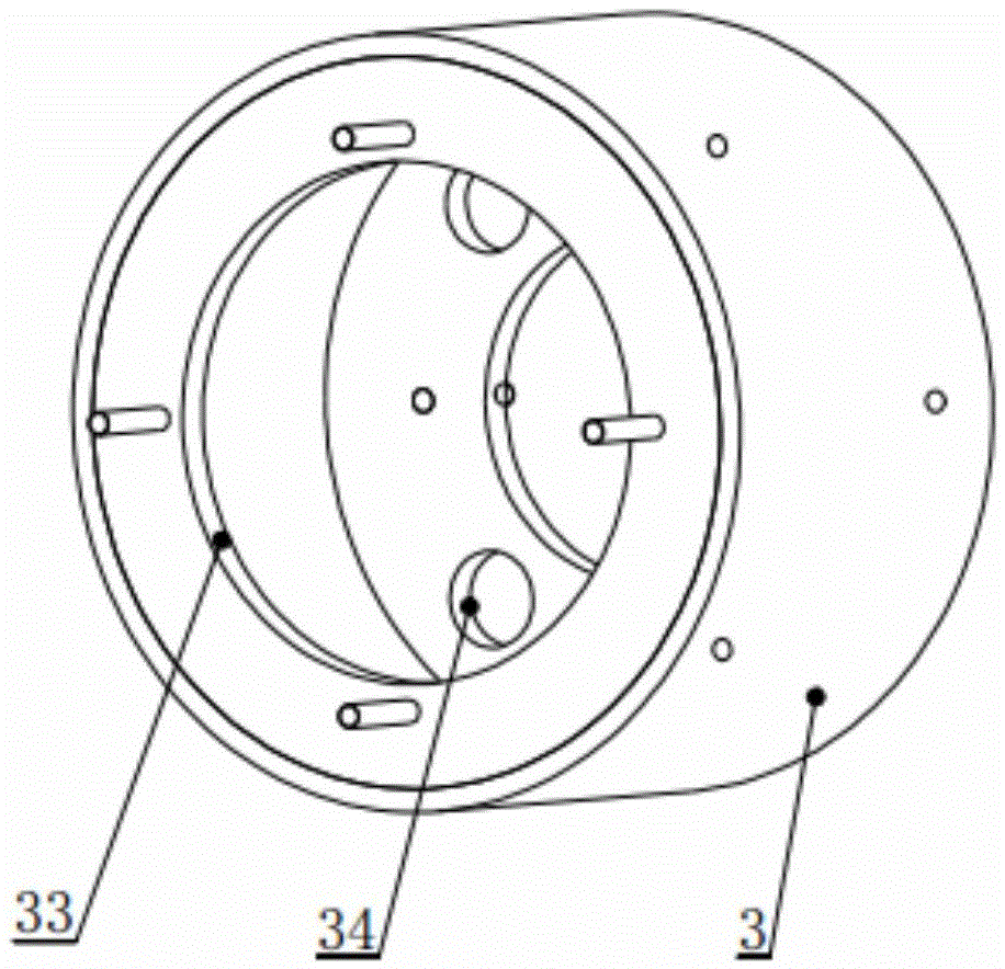
[0042] see in conjunction figure 2 and image 3 , the gas mixing device of this embodiment is arranged in the gas mixing chamber 3, the gas mixing chamber 3 is a cylindrical shell structure, the end is connected to the burner metal fiber furnace head thro...

Embodiment 2

[0046] see in conjunction Figure 5a , Figure 5b The difference between this embodiment and Embodiment 1 is that the baffle plate 312 of the gas outlet assembly in the figure is located at the front end of the gas outlet 313 of the gas outlet pipe 311, and all the gas outlets 313 and air outlets 33 are located at the front end of the gas outlet 313. On the same side of the plate 312, the gas outlet 313 in the present embodiment adopts Kongshi gas outlet, that is, a number of circular holes are evenly opened on the same circumference of the gas outlet pipeline, and the air provided by the burner fan and the gas inlet joint respectively It is mixed with the gas in front of the baffle, and then uniformly disturbed by the baffle to quickly form a uniform mixed gas that is beneficial to combustion.

[0047] The way of gas outlet in this embodiment and embodiment 1 can be adjusted interchangeably.

[0048] Further, a gas mixing part 32 is also provided in the middle of the gas mi...

Embodiment 3

[0051] see Figure 8 and Figure 9 The difference between this embodiment and the previous embodiments is that the air mixing chamber 3 and the cylinder 62 in this embodiment are two-stage double cylinders connected coaxially and integrally, and the diameters of the two sections connected by the axial direction are different. The cylinder of the air mixing chamber is fixedly connected to the air outlet of the burner fan through a flange connection. The internal air mixing device can be arranged with reference to Embodiment 1 and Embodiment 2, and one end of the cylinder connected to the flange assembly The welding furnace head connects the flange 63. This embodiment provides a simplified mode, which can save a connecting flange, and is suitable for the case where the ignition pin is short.

[0052] see Figure 10a , 10b , the diagrams are the combustion effect diagrams of the existing burner head, the flame is darker at the inlet end of the burner, which shows that the com...


PUM


Abstract

Disclosed is a gas mixing device of a burner. The gas mixing device of the burner comprises a gas mixing cavity, wherein a burner fan and a metal fiber burner head are communicated through the gas mixing cavity, and a fuel gas outlet assembly is arranged in an air outlet, connected with the burner fan, of the gas mixing cavity. The fuel gas outlet assembly comprises a fuel gas outlet pipe and a baffle, wherein the fuel gas outlet pipe is arranged in the air outlet and is communicated with a fuel gas inlet connector of the burner, and the baffle stretches into the gas mixing cavity from the air outlet of the burner fan through the fuel gas outlet pipe. According to the invention, the length of a non-combustion area of the burner head is effectively reduced, uniform gas mixing can be achieved in the short distance, the flame distribution is uniform, the capacity of the gas mixing device for adapting to different brands of burners is quite high, the problem that the difference of the air volumes in the peripheral direction of burner heads of different burners is large can be conveniently solved by the same structure, uniform distribution of flames of the burner head is facilitated, the pressure relief function is fulfilled under the condition of tempering, the phenomenon that a safety accident happens due to the damage to the burner fan is avoided, the equipment installation and running space is saved, and the cost is reduced.

Description

technical field [0001] The invention belongs to the technical field of gas equipment, and in particular relates to a gas mixing device for an ultra-low nitrogen oxide emission burner. Background technique [0002] The existing traditional boiler is equipped with a gun burner. After the gun burner is transformed into a metal fiber surface combustion method, it has a special structure of the metal fiber burner, so that the combustion occurs on the surface of the metal fiber fabric, and the combustion flame is short and compact. , the smaller boiler furnace size can meet the needs, and the combustion is uniform, which can effectively reduce the generation of NOx, so it gradually begins to be used more and more. [0003] Most of the lance burners transformed into metal fiber surface combustion are pre-mixed after the fan, and a long mixing distance is required for uniform gas mixing. After the boiler is transformed into a gun-type burner with a metal fiber surface combustion me...

Claims


Application Information

Patent Timeline
Patent Type & Authority Applications(China)
IPC IPC(8): F23D14/02F23D14/62
CPCF23D14/02F23D14/62
Inventor 王畅辉罗磊李鸿黄俊杰
Owner HUNAN HUITONG ADVANCED MATERIALS
Why Eureka
Try Eureka