Non-contact induction power supply device used for ultrasonic milling processing

A technology of milling processing and induction power supply, which is applied to circuit devices, electrical components, etc., can solve the problems of low rotation stability of rotating parts, limited rotation speed, and inability to ensure stable and high reliability ultrasonic milling operations.

Active Publication Date: 2016-04-27
BEIHANG UNIV
View PDF6 Cites 9 Cited by
  • Summary
  • Abstract
  • Description
  • Claims
  • Application Information

AI Technical Summary

Problems solved by technology

[0002] In the traditional ultrasonic milling process, the ultrasonic vibration system mostly adopts the contact power supply mode. For example, the power supply mode of the conductive slip ring has four major defects: First, the slip ring is always in contact with the power supply brush, resulting in serious wear or damage, which cannot ensure stability. and high-reliability ultrasonic milling operations; secondly, due to the contact electric spark of the power supply brush, the stable and high-reliability ultrasonic milling processing operation cannot be guaranteed; thirdly, in order to reduce the wear or damage of the slip ring, it has In addition, after adding the sealing ring, the speed cannot be increased, so it cannot meet the requirements of high-speed rotation of the ultrasonic milling spindle; the fourth is that there is a mechanical connection between the rotating part and the stationary part in the power supply device, which cannot meet the automatic tool change requirements of the CNC machining center. Require
[0005] 1) It cannot meet the requirements of automatic tool change of CNC machining center;
[0006] 2) The rotation stability of the rotating part is low, and after being installed on the standard spindle ultrasonic milling tool holder, it cannot meet the high-speed rotation requirements of the ultrasonic milling spindle;
[0007] 3) The resonance compensation scheme adopted by the secondary circuit has theoretical flaws, the transmission capacity of the non-contact induction power supply device is limited, and it cannot meet the working requirements of the high-power ultrasonic vibration system

Method used


Image

  • Non-contact induction power supply device used for ultrasonic milling processing
  • Non-contact induction power supply device used for ultrasonic milling processing
  • Non-contact induction power supply device used for ultrasonic milling processing

Examples


Embodiment 1

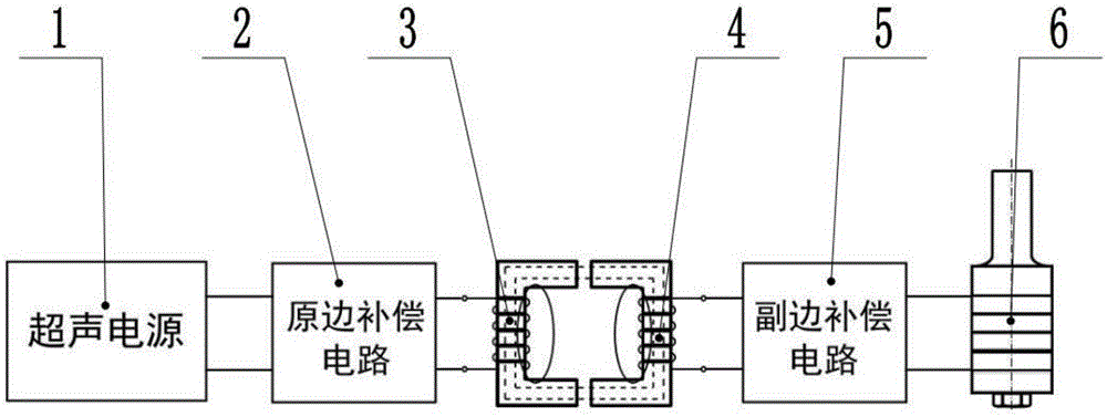
[0120] attached Figure 9 It is a specific embodiment of a non-contact inductive power supply device for ultrasonic milling of the present invention.

[0121] According to attached Figure 9 It can be seen that the non-contact inductive power supply device consists of two parts, the primary side 3 and the secondary side 4 .

[0122] The primary side 3 is fixedly mounted on the spindle base 7 of the CNC machining center and connected to the ultrasonic power supply 1; the secondary side 4 is fixedly mounted on the standard spindle ultrasonic milling tool handle 9 and integrated with the standard spindle ultrasonic milling cutter The ultrasonic vibration system 6 inside the handle 9 is connected.

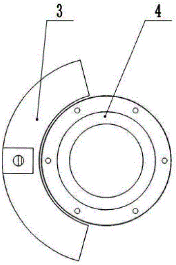
[0123] As shown in accompanying drawing 2 (a), the spatial positional relation of described primary side 3 and described secondary side 4 is arranged as inner and outer concentric circles, and described primary side 3 is outside described secondary side 4; There is no mechanical con...


PUM


Abstract

The invention discloses a non-contact induction power supply device used for ultrasonic milling processing. The non-contact induction power supply device mainly comprises a primary side and a secondary side, wherein the spatial position relationship of the primary side and the secondary side is arranged as an inner and outer concentric circle type, the primary side and the secondary side do not have any mechanical connection, and the primary side is of an incomplete-ring columnar structure which is only provided with 2/5 circumference on a circumferential direction. Through the optimal design of the secondary side, under a situation that no compensation components are additionally arranged, mutual compensation is realized under the working vibration frequency of an ultrasonic vibration system by the leak inductance of a secondary side coil and the equivalent capacitive reactance of an ultrasonic vibration system. The non-contact induction power supply device has the advantages of compact structure and small rotational inertia, can carry out expansion installation, and can meet the working requirements that the ultrasonic milling processing can automatically carry out tool change, a main shaft rotates at a high speed and the ultrasonic vibration system is large in power. The power supply requirements of elliptical ultrasonic milling processing also can be met if two groups of non-contact induction power supply devices are installed.

Description

technical field [0001] The invention relates to a non-contact inductive power supply device, in particular to a non-contact inductive power supply device for ultrasonic milling. The invention belongs to the technical field of ultrasonic milling. Background technique [0002] In the traditional ultrasonic milling process, the ultrasonic vibration system mostly adopts the contact power supply mode. For example, the power supply mode of the conductive slip ring has four major defects: First, the slip ring is always in contact with the power supply brush, resulting in serious wear or damage, which cannot ensure stability. and high-reliability ultrasonic milling operations; secondly, due to the contact electric spark of the power supply brush, the stable and high-reliability ultrasonic milling processing operation cannot be guaranteed; thirdly, in order to reduce the wear or damage of the slip ring, it has In addition, after adding the sealing ring, the speed cannot be increased...

Claims


Application Information

Patent Timeline
Patent Type & Authority Applications(China)
IPC IPC(8): H02J50/10H02J50/70
Inventor 姜兴刚邵瑞杰张德远王凯强
Owner BEIHANG UNIV
Why Eureka
Try Eureka