Pollutant pretreating tower condensing based on flue gas

A technology for flue gas condensation and pollutants, which is applied in the direction of air quality improvement, the use of liquid separation agents, and the separation of dispersed particles. Effects of flow resistance, reduction of tray layers, and simplification of internal structure

Active Publication Date: 2016-05-04
XI AN JIAOTONG UNIV
View PDF5 Cites 10 Cited by
  • Summary
  • Abstract
  • Description
  • Claims
  • Application Information

AI Technical Summary

Problems solved by technology

In addition, the design of the desulfurization tower adopts two-way spraying, or is equipped with trough distributors, air distribution perforated plates, flow equalization rings, swivel coupling devices, liquid holding uniform plates, inclined plate collectors, gas gathering rings, etc. to improve desulfurization Efficiency, cumbersome process, complicated process
These designs and modifications make the flue gas flow resistance in the desulfurization tower more and more large, the fan consumes a lot of energy, and even leads to insufficient power, and the flue gas cannot complete the journey in the desulfurization tower

Method used


Image

  • Pollutant pretreating tower condensing based on flue gas

Examples


Embodiment Construction

[0020] In order to make the purpose, technical solution and advantages of the present invention more clear and concise, the present invention will be further described in detail below in conjunction with the accompanying drawings and embodiments. It should be understood that the specific embodiments described here are only used to explain the present invention, not to limit the present invention.

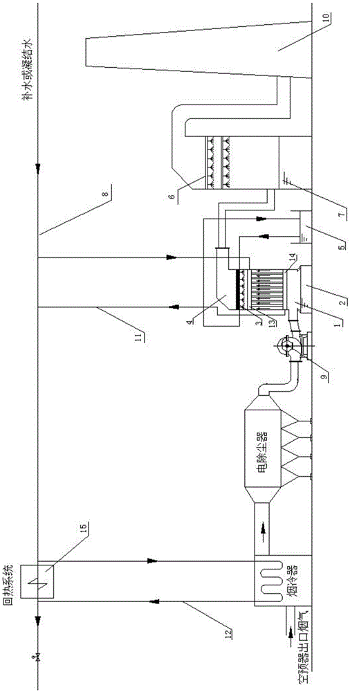
[0021] like figure 1 As shown, the present invention is a pollutant pretreatment tower based on flue gas condensation. The pollutant pretreatment tower 4 is arranged between the electrostatic precipitator and the desulfurization tower 7, and its entrance is connected with the static electricity through the induced draft fan or the booster fan 9. The outlet of the dust collector is connected, the outlet is connected with the desulfurization tower 7 , and the outlet of the desulfurization tower 7 is connected with the chimney 10 . A dense condensation tube bundle 1 is installed insid...


PUM


Abstract

The invention provides a pollutant pretreating tower condensing based on flue gas. The pollutant pretreating tower comprises a condensation pipe bundle, an alkaline water storage slot, a spraying device, an alkaline liquor circulating sedimentation tank, a condensation pipe bundle external circulating pipeline, upper and lower headers and the like. The flue gas passes through a flue gas cooler and an electrostatic precipitator in sequence and enters the pollutant pretreating tower; heat exchange between the flue gas and condensation water, boiler feed water or replenished water, in the condensation pipe bundle, at about 20 to 38 DEG C occurs, so that steam in the flue gas is cooled and condensed; acid gases such as SO2, CL2, F2 and NOx are reacted with water to generate acid solutions such as H2SO3, H2SO4, HCL and HF; the acid solutions are collected by the alkaline liquor circulating sedimentation tank; meanwhile ammonia gas escaped from the flue gas is also chemically reacted with the acid solutions, so that the escaped ammonia gas can be removed. By arranging the condensation type pollutant pretreating tower disclosed by the invention, pollutants can be removed partially; the structure of a desulfurizing tower is simplified; the pressure of the desulfurizing tower is relieved; the flow resistance of the flue gas is greatly reduced so as to reduce the power consumption of a fan and save energy resources; according to the pollutant pretreating tower disclosed by the invention, the flow path of the flue gas is basically not changed, the change range is small, and the cost is reasonable.

Description

technical field [0001] The invention belongs to the technical field of comprehensive treatment of flue gas pollutants, and in particular relates to a pollutant pretreatment tower based on flue gas condensation. Background technique [0002] At present, coal-fired power plants and coal-fired industrial processes widely use coal-based boilers and kilns, and the coal-fired industrial processes are large in volume and wide in scope, most of which are located in the center of the city or in the suburbs, and the comprehensive treatment of pollutants is difficult. top priority. The thermal power industry first proposed to meet the gas emission standards: PM / SO 2 / NO X Respectively should reach 10 / 35 / 50mg / m 3 , and then put forward ultra-low emission targets one after another: PM / SO 2 / NO X Respectively reach 5 / 20 / 35mg / m 3 And at the same time make the SO in the flue gas 3 / Hg reaches 5 / 0.005mg / m 3 . [0003] Due to the large deviation between the current coal quality compo...

Claims


Application Information

Patent Timeline
Patent Type & Authority Applications(China)
IPC IPC(8): B01D53/78B01D53/60B01D53/68B01D53/58B01D47/05
CPCB01D47/05B01D53/58B01D53/60B01D53/68B01D53/78B01D53/002Y02A50/20
Inventor 王云刚孙一睿贾晓琳李卫东赵钦新
Owner XI AN JIAOTONG UNIV
Why Eureka
Try Eureka