
A hanger for chemical plating

A technology of electroless plating and hanger, which is applied in the direction of liquid chemical plating, metal material coating process, coating, etc., and can solve the problem of mass production of difficult-to-resistance copper foil, affecting the uniformity of resistance plating, and low thickness of copper foil, etc. problems, to achieve the effect of mass production, easy to use widely, and increase the area

Active Publication Date: 2018-07-27
AKM ELECTRONICS INDAL PANYU
View PDF9 Cites 0 Cited by
  • Summary
  • Abstract
  • Description
  • Claims
  • Application Information

AI Technical Summary

Problems solved by technology

However, the thickness of copper foil required for the manufacture of resistive copper foil is extremely low, generally only 1 / 2 oz. During the plating process, the high temperature generated by the plating solution tends to cause it to curl and overlap. Placing the plated parts directly in it is prone to wrinkles, and it is easy to directly touch the hanging basket and cause scratches. These unfavorable factors directly affect the uniformity of the resistance plating layer
In addition, it is difficult to achieve mass production of resistive copper foil using the current electroless plating process

Method used


Image

  • A hanger for chemical plating
  • A hanger for chemical plating
  • A hanger for chemical plating

Examples


Embodiment 1

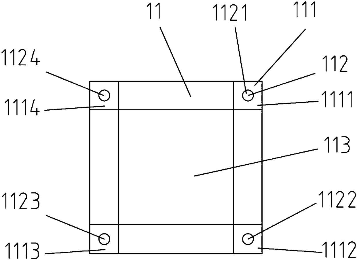
[0035] This embodiment discloses a hanger for electroless plating, such as Figure 1~4 , Figure 5 , Figure 7 As shown, it includes:

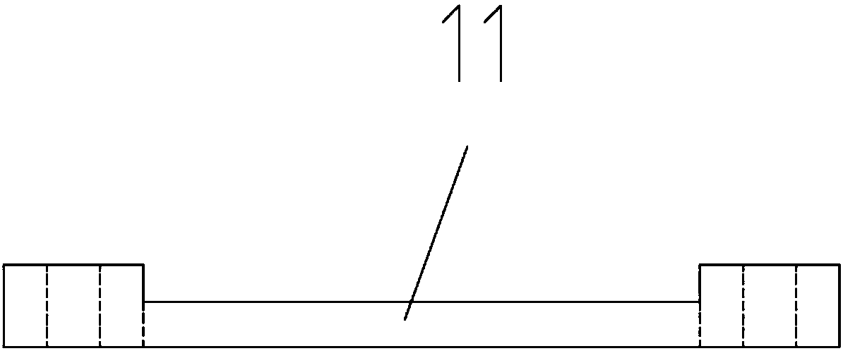
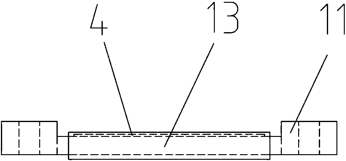
[0036] Clamping part 1, it comprises a plurality of substrates 11, substrate fixing device 12 and plating parts fixing device 13 that place plated part 4 usefulness, substrate 11 is provided with boss 111, and boss 111 is provided with through hole 112, and substrate 11 is also provided with a hollowed-out area 113, and the plated parts 4 on the fixed substrate 11 are fixed by the plated part fixing device 13. A plurality of substrates 11 are stacked and the plated parts 4 on the substrate 11 are isolated from each other. A plurality of stacked substrates 11 are bound together to form a clamping portion 1;

[0037] The accommodating part 2 includes a basket 21, the holding part 1 is placed in the basket 21, and the basket 21 plays a role in containing and supporting the whole holding part 1 (including the parts on the holding part 1) in the...

Embodiment 2

[0049] This embodiment discloses another hanger for electroless plating, such as Figure 1~4 , Figure 6 , Figure 8 Shown, its main difference with embodiment 1 is:

[0050] In this embodiment, eight substrates 11 are stacked one by one, and a boss 111 is provided on one side of each substrate 11, the boss 111 of the uppermost substrate 11 faces downward, and the bosses 111 of the remaining substrates 11 all face upward. The plating fixtures 13 on each substrate 11 are on the same vertical plane. By stacking the substrates 11 in this way, each plating piece 4 on each substrate 11 can be protected by the substrate 11 from external damage, which is beneficial to improve the effect of electroless plating.

[0051] The rest of the structure and parts connection relationship of the electroless plating hanger disclosed in this embodiment are completely consistent with those in Embodiment 1, and will not be repeated here.

[0052] In order to facilitate a better understanding of...


PUM


Abstract

The invention discloses a hanger for chemical plating, which is characterized by comprising a clamping part, a containing part and a lifting handle part, wherein the clamping part comprises a plurality of base plates for placing plating articles, a base plate fixing device and a plating article fixing device; each base plate is provided with a lug boss which is provided with a through hole; each base plate is also provided with a hollow region; the plating article fixing device is used for fixing the plating articles on the base plate; the base plates are superposed, so that the plating articles on the base plates are mutually separated; the base plate fixing device penetrates through the through hole so as to bind the superposed base plates into an integral body, thereby forming the clamping part; the containing part comprises a basket; the clamping part is arranged in the basket; the lifting handle part comprises a lifting hook; and the lifting hook is connected to the containing part. When the hanger is applied to chemical plating, the obtained resistance coating has high uniformity, the product quality is greatly improved, and the mass production of resistance-type copper foil can be implemented. Besides, the hanger has the advantages of simple structure and low manufacturing cost.

Description

technical field [0001] The invention belongs to the technical field of process equipment, and in particular relates to a hanger for electroless plating. Background technique [0002] The resistance type copper foil is prepared by plating a layer of resistance alloy material (such as nickel-phosphorus alloy or nickel-chromium alloy, etc.) on the copper foil. In the prior art, resistive copper foil is mainly made by electroplating process or vacuum sputtering process. However, resistive copper foil is mainly used as an embedded resistor, and the requirements for the uniformity of the plating layer are very high. However, at the current stage, there are certain defects whether it is through the electroplating process or the vacuum sputtering process. For example, the uniformity of the coating thickness of the resistive copper foil prepared by the electroplating process is not easy to control; the resistive copper foil prepared by the vacuum sputtering process has very strict ...

Claims


Application Information

Patent Timeline
Patent Type & Authority Patents(China)
IPC IPC(8): C23C18/16
CPCC23C18/163
Inventor 王锋伟张仕通
Owner AKM ELECTRONICS INDAL PANYU
Learn More