Configuration method for cathode buses of electrolytic baths with controllably adjustable vertical magnetic fields and structure adopting method

A vertical magnetic field and cathode busbar technology, which is applied in the field of cathode busbar configuration of aluminum electrolytic cells, can solve the problems of excessive magnetic field compensation in electrolytic cells, abnormal fluctuations in electrolytic cells, and different magnetic field compensation requirements. The method is simple and the overall stability is improved. The effect of the indicator

Inactive Publication Date: 2016-05-04
CENT SOUTH UNIV
View PDF7 Cites 2 Cited by
  • Summary
  • Abstract
  • Description
  • Claims
  • Application Information

AI Technical Summary

Problems solved by technology

Obviously, due to the different states and locations of the electrolytic cells in the series, such as the electrolytic cell at the end of the factory building and the electrolytic cell in the middle of the factory building, the electrolytic cell in normal operation, and the electrolytic cell with sediment at the bottom of the furnace, the magnetic field environment They are all completely different, and at the same time, the requirements for magnetic field compensation will also be quite different. If the same configuration is still used, the result will be that the magnetic field compensation of some electrolytic cells is over-compensated, while the other part is under-compensated, which will lead to abnormal fluctuations in the electrolytic cell within the series. , which seriously affects the normal production. This phenomenon is not uncommon in the production of aluminum electrolysis.

Method used


Image

  • Configuration method for cathode buses of electrolytic baths with controllably adjustable vertical magnetic fields and structure adopting method
  • Configuration method for cathode buses of electrolytic baths with controllably adjustable vertical magnetic fields and structure adopting method
  • Configuration method for cathode buses of electrolytic baths with controllably adjustable vertical magnetic fields and structure adopting method

Examples


Embodiment Construction

[0030] The present invention will be further described below in conjunction with accompanying drawing.

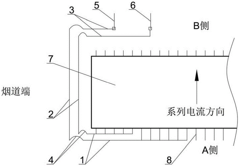
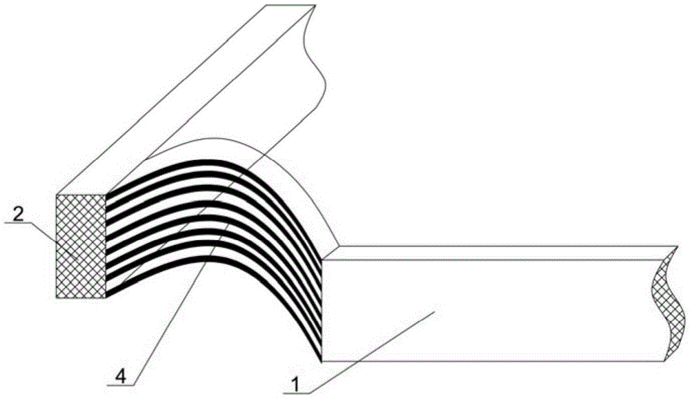
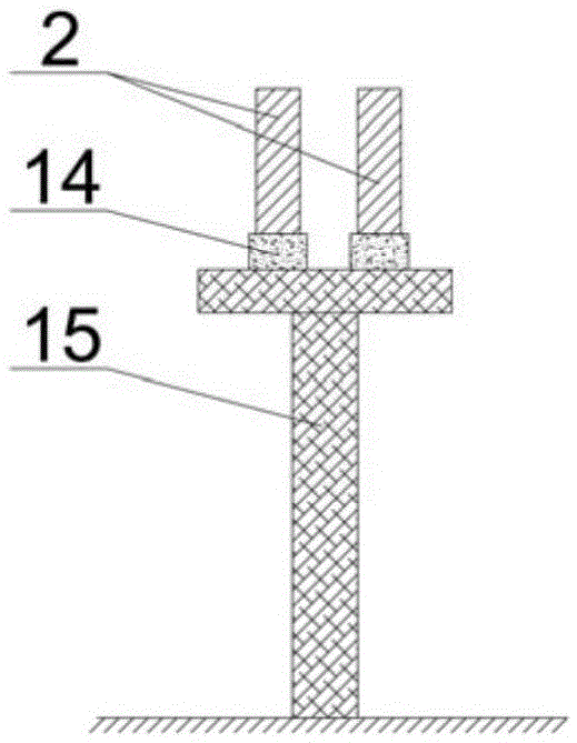
[0031] see figure 1 and figure 2 , a configuration method and structure of the cathode bus bar of an electrolytic cell with a controllable and adjustable vertical magnetic field. There are three parts on the outlet side part 3 of the end busbar, the inlet side part 1 of the end busbar and the end part 2 of the end busbar, and the vertical magnetic field adjustment is adopted between the end part 2 of the end busbar and the outlet side part 3 of the end busbar The soft busbar 4 is connected so that the end part 2 of the end busbar can move as needed along the vertical direction and the horizontal direction, so as to realize the dynamic adjustment of the most important end compensation busbar of the aluminum electrolytic cell. The number of busbars flowing through the end is consistent with the existing design. The number of busbars flowing through the end is two or four, ...


PUM

PropertyMeasurementUnit
thicknessaaaaaaaaaa
lengthaaaaaaaaaa

Abstract

The invention discloses a configuration method for cathode buses of electrolytic baths with controllably adjustable vertical magnetic fields and a structure adopting the method. Each cathode bus flowing through an aluminum outlet end and a flue end is divided into an end bus electricity supply side part, an end bus tip part and an end bus electricity discharge side part which are connected through vertical magnetic field adjusting soft buses. The end bus tip parts can move in the vertical direction and the horizontal direction as needed, and dynamic adjustment of the most important end compensation buses of the aluminum electrolytic baths is achieved. The method is simple and efficient. The designed buses can not only meet the requirement for stable operation of magnetic fluid of the large aluminum electrolytic baths but also achieve configuration of the magnetic fields of the electrolytic baths according to demands in a series, and therefore the overall stability index of the electrolytic baths is greatly improved.

Description

technical field [0001] The invention relates to a method for arranging cathode busbars of an aluminum electrolytic cell, in particular to a method for arranging cathode busbars of an electrolytic cell with a controllable and adjustable vertical magnetic field. The invention also relates to the structure of the electrolytic cell cathode bus bar configuration method using the controllable adjustment of the vertical magnetic field. technical background [0002] In the aluminum electrolysis series, all the electrolytic cells are connected in series, and the bus bar mainly undertakes the function of transmitting the current from the cathode rod of the upstream electrolytic cell to the anode rod of the downstream electrolytic cell. At the same time, the bus bar of the electrolytic cell, especially the cathode bus bar, plays a decisive role in the stability of the electrolytic cell. Different cathode configurations will produce completely different magnetic field configurations and...

Claims


Application Information

Patent Timeline
Patent Type & Authority Applications(China)
IPC IPC(8): C25C3/16C25C3/20
CPCC25C3/16C25C3/20
Inventor 张红亮李劼孙珂娜梁金鼎冉岭肖劲张凯
Owner CENT SOUTH UNIV
Why Eureka
Try Eureka