Circuit and method for weak current detection

A weak current and detection circuit technology, which is applied in the direction of measuring current/voltage, only measuring current, measuring devices, etc., can solve the problems of unable to perform current detection, affect the accuracy of current detection, and low detection accuracy, and expand the current measurement range , Improve the measurement accuracy, the effect of high common mode rejection ratio

Inactive Publication Date: 2016-05-04
THE 41ST INST OF CHINA ELECTRONICS TECH GRP
View PDF3 Cites 24 Cited by
  • Summary
  • Abstract
  • Description
  • Claims
  • Application Information

AI Technical Summary

Problems solved by technology

[0003] As the detection current decreases, the influence of the input impedance of the operational amplifier on the detected current will increase, seriously affecting the current detection accuracy
For cutting-edge products such as semiconductor analyzers, the current detection sensitivity requirements are often as high as nA level, or even as high as pA level. The traditional current detection method not only has low detection accuracy, but even cannot perform current detection.

Method used


Image

  • Circuit and method for weak current detection
  • Circuit and method for weak current detection
  • Circuit and method for weak current detection

Examples


Embodiment 1

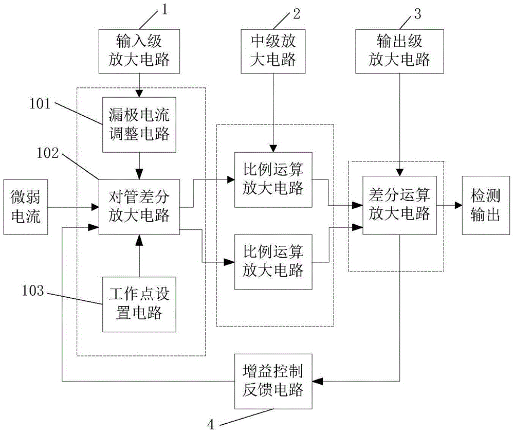
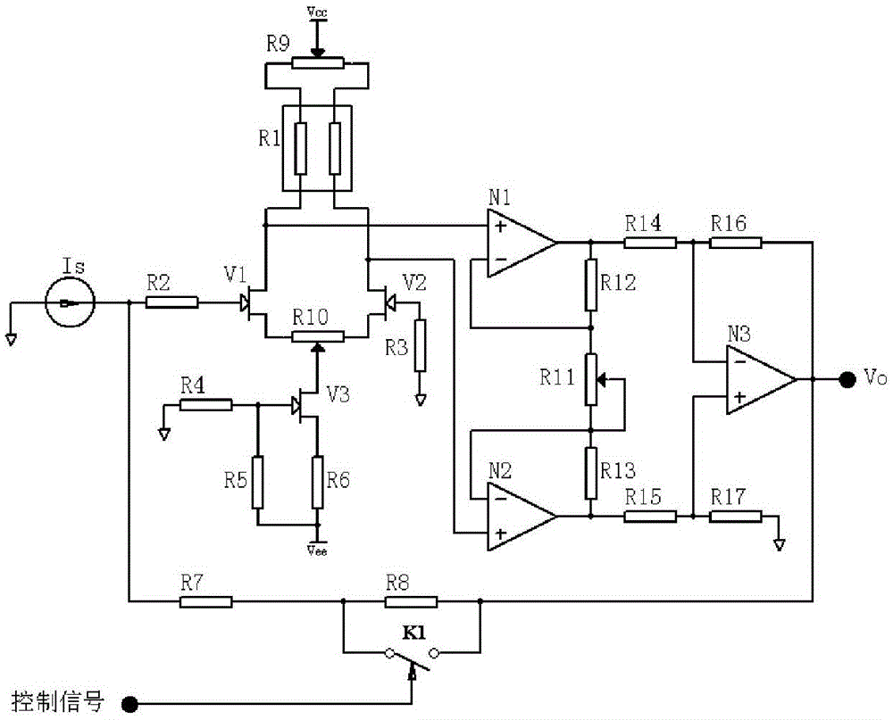
[0038] Such as figure 1 As shown, it includes an input-stage amplifier circuit 1, an intermediate-stage amplifier circuit 2, and an output-stage amplifier circuit 3. The input-stage amplifier circuit 1 includes a pair-to-tube differential amplifier circuit 102 composed of junction field effect transistors; The circuit 2 adopts two sets of proportional operational amplifier circuits with in-phase input; the output stage amplifying circuit 3 adopts a differential operational amplifier circuit.

[0039] The weak current is input to the input terminal of the pair tube differential amplifier circuit 102, and the pre-differential amplification is performed to increase the input impedance. At the same time, the current signal is converted into a voltage signal to facilitate the signal processing of the back-end circuit; the output of the pair tube differential amplifier circuit 102 The differential voltage signal output by the terminal is respectively input to the intermediate amplifier...

Embodiment 2

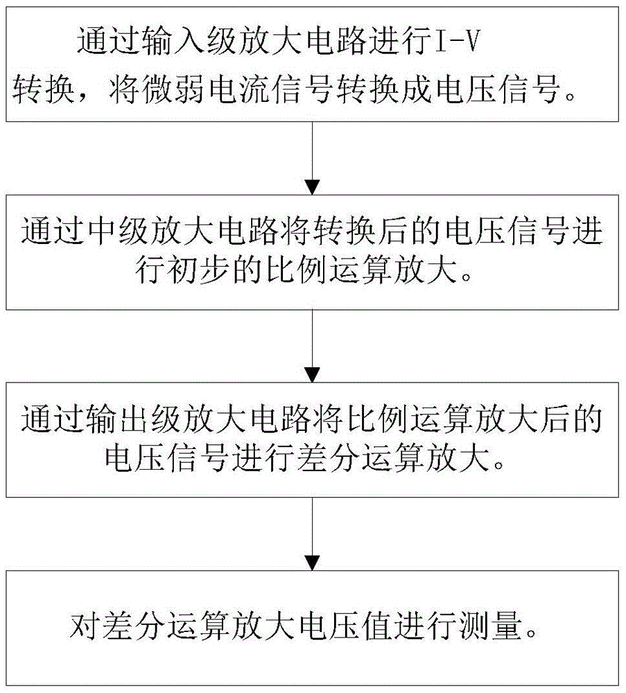
[0056] On the basis of the above embodiments, the present invention provides a weak current detection method (such as image 3 As shown), it is used to detect weak current, where, follow the steps below:

[0057] Step 1: I-V conversion is performed through the input stage amplifier circuit to convert the weak current signal into a voltage signal;

[0058] Step 2: Perform a preliminary proportional amplifying of the converted voltage signal through an intermediate amplifier circuit;

[0059] Step 3: Perform differential operational amplification on the voltage signal after the proportional operational amplification by the output stage amplifying circuit to obtain the differential operational amplified voltage value;


PUM


Abstract

The invention discloses a circuit and a method for weak current detection and belongs to the current detection field. Geminate field effect transistors are employed by an input end to form a difference amplifier, and I-V conversion of a weak current is carried out; a voltage signal after conversion is sent to two sets of proportion operation circuits having symmetric in-phase input modes for proportion operation amplification; difference operation amplification of the voltage signal after proportion operation amplification is carried out, and a difference operation amplification voltage magnitude is measured. According to the method and the device, the junction type geminate field effect transistors are employed to form the difference amplifier as an input level, so input impedance is improved, and the relatively high common-mode inhibition ratio is acquired; the precise proportion operation circuit structures in the symmetric in-phase input modes are employed as the middle level, input impedance is further improved, and measurement precision is improved; the multiple operation amplifier difference amplification detection technology is employed, conflicts of useful-signal weakness and relatively high common-mode interference can be effectively solved, and high gain, high input resistance and the high common-mode inhibition ratio of the detection circuit are realized.

Description

Technical field [0001] The invention belongs to the field of current detection, and specifically relates to a weak current detection circuit and method. Background technique [0002] The existing weak current detection generally uses the current sampling method, that is, the current signal is converted into a voltage sampling signal through a special precision sampling resistor, the voltage sampling signal is compared with the reference voltage, and the feedback control is performed through the operational amplifier to achieve the current Detection function. [0003] As the detection current decreases, the impact of the input impedance of the operational amplifier on the detected current will increase, seriously affecting the current detection accuracy. For cutting-edge products such as semiconductor analyzers, the current detection sensitivity requirements are often as high as nA, or even as high as pA. Using traditional current detection methods, not only the detection accuracy ...

Claims


Application Information

Patent Timeline
Patent Type & Authority Applications(China)
IPC IPC(8): G01R19/00
CPCG01R19/0092
Inventor 王文廷张永坡李斌王群李雷王俊
Owner THE 41ST INST OF CHINA ELECTRONICS TECH GRP
Why Eureka
Try Eureka