
Fault recording device on the basis of double-CPY parallel wave recording storage

A technology of a fault recording device and a CPU module, applied in the field of power systems, can solve problems such as the inability to meet the processing capacity and storage capacity, the low performance of the CPU processor, and the inability to export the collected data, achieving excellent performance, convenient analysis and processing, and solving problems. Effects of Access Violation

Active Publication Date: 2016-05-04
CHENGDU FUHE POWER AUTOMATION COMPLETE EQUIP
View PDF5 Cites 12 Cited by
  • Summary
  • Abstract
  • Description
  • Claims
  • Application Information

AI Technical Summary

Problems solved by technology

[0010] 3) The application program and recording data of the faulty wave recording device are stored in one disk, and frequent reading and writing of the hard disk leads to damage to the physical medium, resulting in device downtime;
[0011] 4) The performance of the CPU processor used in the analysis and processing unit of the fault recording device is relatively low, the speed is slow, and the storage capacity supported is small, which has been unable to meet the higher requirements of the large-capacity power system on the processing capacity and storage capacity of the fault recording device. high requirements;
[0012] 5) There is no hardware compression function, and the hard disk uses a 2.5-inch notebook hard disk;
[0013] 6) The collected data cannot be exported to other devices, and the system expandability is poor

Method used


Image

  • Fault recording device on the basis of double-CPY parallel wave recording storage
  • Fault recording device on the basis of double-CPY parallel wave recording storage

Examples


Embodiment Construction

[0034] The present invention will be further described below in conjunction with accompanying drawing:

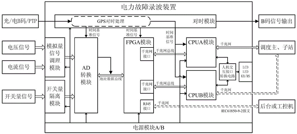
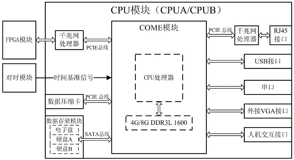
[0035] Such as figure 1 and figure 2 As shown, the fault recording device based on dual CPU parallel recording and storage of the present invention includes an analog signal conditioning module, a switch isolation module, an AD conversion module, a time synchronization module, an FPGA module, two CPU modules and a power supply module. The CPU module is the core of the fault recording device. A fault recording device is redundantly controlled by dual CPU modules. The hardware structure of the two CPU modules is exactly the same, and they are redundant with each other. There is no primary or secondary, and the versatility is good; The design ensures the safe operation of the system and improves the reliability of the system operation.

[0036] The following is a detailed introduction to each part of the module:

[0037] The analog signal conditioning module is used to con...


PUM


Abstract

The present invention discloses a fault recording device on the basis of a double-CPY parallel wave recording storage. The device provided by the invention comprises a simulation signal conditioning module, a switching value isolation module, an AD conversion module, a time setting module, a FPGA module, a power supply and two CPY modules. The two CPU modules communicate with the FPGA module through each kilomega network bus; the FPGA module is provided with a RJ45 interface, and the RJ45 interface of the FPGA module is able to transmit real-time collection data in an IEC61850-9-2 message format to a background through a kilomega network or an industrial control computer; and the time setting module is configured to provide time reference signals for the AD conversion module, the FPGA module and two CPU modules at the same time, and the power supply module supplies power for the whole fault recording device. The technical problems are solved that the fault recording device has low operation reliability, unreasonable data storage and the like in the prior art, and the device operation, the storage reliability and the data transmission rate are improved; and moreover, the fault recording device on the basis of a double-CPY parallel wave recording storage has advantages of high performances, good compatibility, high reliability, good stability, wide application and the like.

Description

technical field [0001] The invention belongs to the technical field of power systems, and in particular relates to a fault recording device based on double CPU parallel recording and storage. Background technique [0002] The fault recording device is an indispensable precision equipment for the dynamic recording process of the power system, and it is an important basis for evaluating the action behavior of relay protection and analyzing the nature and cause of equipment faults. Its main task is to automatically and accurately record the changes of various electrical quantities in the whole process of the fault when a fault occurs in the power system, and analyze and process the recorded electrical quantities, so as to accurately judge and deal with the fault and ensure the safety, stability and reliability of the power system. run. [0003] With the promulgation of the power system IEC61850 standard, the rapid development of computer technology, optical fiber, and network ...

Claims


Application Information

Patent Timeline
IPC IPC(8): G01R31/00
CPCG01R31/00
Inventor 赵小凤罗建国程加强董龙钟华兰
Owner CHENGDU FUHE POWER AUTOMATION COMPLETE EQUIP
Learn More