Light sensing apparatus

A light-sensing and photosensitive layer technology, which is applied to electrical components, electric solid devices, circuits, etc., can solve the problems of cost reduction of light-sensing devices, difficulty in thinning the thickness of light-sensing devices, and signal interference, etc., to achieve improved signal The effect of interference problems

Active Publication Date: 2016-05-04
AU OPTRONICS CORP
View PDF5 Cites 18 Cited by
  • Summary
  • Abstract
  • Description
  • Claims
  • Application Information

AI Technical Summary

Problems solved by technology

However, this is not conducive to the cost reduction of the photo-sensing device, and it is not easy to reduce the thickness of the photo-sensing device.
In addition, although the backlight module has adopted a prism sheet, part of the light beam emitted by the backlight module will still be transmitted to the photosensitive unit, causing signal interference

Method used


Image

  • Light sensing apparatus
  • Light sensing apparatus
  • Light sensing apparatus

Examples


Embodiment Construction

[0073] Below in conjunction with accompanying drawing, structural principle and working principle of the present invention are specifically described:

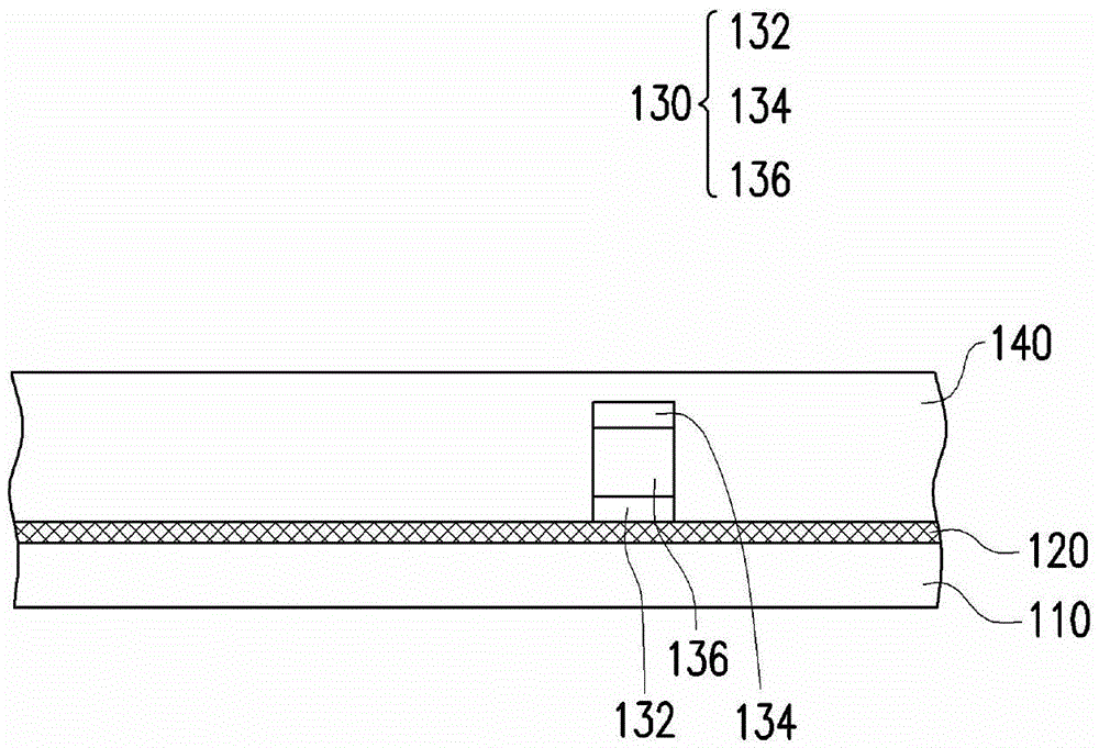
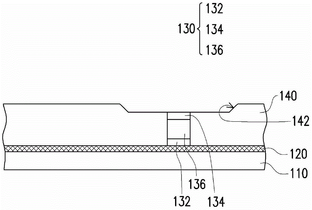
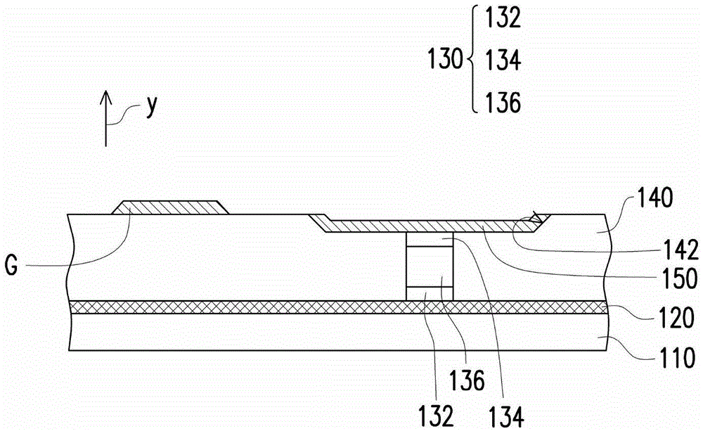
[0074] Figure 1A to Figure 1FIt is a schematic cross-sectional view of the manufacturing process of the photo-sensing device according to an embodiment of the present invention. Please refer to Figure 1A , firstly, a first substrate 110 is provided. The first substrate 110 may be a light-transmitting first substrate or an opaque / reflective first substrate. For example, the material of the light-transmitting first substrate can be glass, quartz, plastic or other suitable materials, and the material of the opaque / reflective first substrate can be wafer, ceramics or other suitable materials, but the present invention does not limit. Next, a first reflective layer 120 is formed to cover the first substrate 110 . In this embodiment, the first reflective layer 120 can be a conductive material, such as: metal, alloy, nitride of...


PUM


Abstract

A light sensing apparatus comprises a first base plate, a light emitting diode, a light sensing unit and a driving element electrically connected with the light sensing unit. The invention relates an arraying relation between the light emitting diode and the light sensing unit on the first base plate.

Description

technical field [0001] The present invention relates to a sensing device, and in particular to a light sensing device. Background technique [0002] Generally speaking, the photo-sensing device includes a photo-sensing panel and a backlight module mounted outside the photo-sensing panel. The backlight module is used for emitting light beams. The light sensing panel is arranged on the transmission path of the light beam. The photosensitive panel includes a first substrate, a plurality of photosensitive units arrayed on the first substrate, and a plurality of active components. Multiple active components are electrically connected with multiple photosensitive units to read signals received by the photosensitive units. [0003] There are many ways to apply the light sensing device. Taking fingerprint scanning as an example, when the user’s finger touches the light sensing device, the peaks and troughs of the fingerprint will reflect light beams with different intensities, so...

Claims


Application Information

Patent Timeline
Patent Type & Authority Applications(China)
IPC IPC(8): H01L31/08
CPCH01L25/167H01L31/08H01L31/173
Inventor 吴宗典郑造时卓恩宗徐文斌刘育荣陈盈宪
Owner AU OPTRONICS CORP
Why Eureka
Try Eureka