Power transmitting device

A technology for power transmission devices and exhaust gas purification devices, which is applied to transmission parts, noise reduction devices, exhaust devices, etc., can solve problems such as deformation, achieve the effects of ensuring contact area, improving rigidity, and preventing large-scale

Inactive Publication Date: 2016-05-04
SUZUKI MOTOR CORP
View PDF5 Cites 3 Cited by
  • Summary
  • Abstract
  • Description
  • Claims
  • Application Information

AI Technical Summary

Problems solved by technology

[0008] However, in the conventional power transmission device described in Patent Document 1, there is a problem that the vibration of the exhaust pipe is directly transmitted to the outer peripheral surface of the case housing the transmission, and local stress is generated on the outer peripheral surface of the case where the support member is fixed. resulting in local deformation

Method used


Image

  • Power transmitting device
  • Power transmitting device
  • Power transmitting device

Examples


Embodiment Construction

[0048] Below, refer to Figure 1 to Figure 9 A power transmission device according to an embodiment of the present invention will be described. In this embodiment, the present invention is applied to a vehicle.

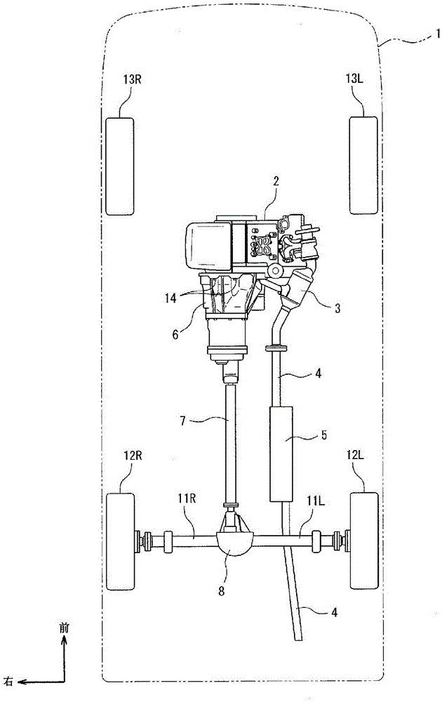
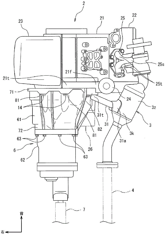
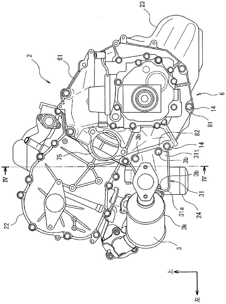
[0049] First, the configuration of the power transmission device of the present embodiment will be described. Such as figure 1 As shown, a vehicle 1 includes an engine 2, an exhaust gas purification device 3, an exhaust pipe 4, a muffler device 5, a power transmission device 6, a transmission shaft 7, a differential device 8, left and right drive shafts 11L, 11R, and left and right rear wheels 12L, 12R. And the left and right front wheels 13L, 13R. In addition, the vehicle 1 includes a plurality of bolts 14 as engine fasteners for fastening the power transmission device 6 to the engine 2 .

[0050] The vehicle 1 includes a so-called FR (Frontengine Reardrive: Front Engine Reardrive) that transmits the power output from the engine 2 disposed on the front side to t...


PUM


Abstract

A power transmitting device comprises a first case (61) for housing a transmission and having an annular engine-fastening section (71) located at the front end of the first case (61) in the front-rear direction, the engine-fastening section (71) being fastened to an engine by bolts. The engine-fastening section (71) has a bracket mounting flange (82), to which a bracket for supporting an exhaust gas purification device is mounted by bolts, the exhaust gas purification device being disposed at a side of the engine-fastening section (71). The bracket mounting flange (82) protrudes outward from a side surface of the first case (61) by a height (h) and a thickness (t), is formed so as to extend vertically and linearly by a length (l), has formed therein an upper engine-fastening hole (82a) and a lower engine-fastening hole (82b), the upper and lower engine-fastening holes (82a, 82b) allowing the bolts to be passed therethrough. An upper bracket-fastening hole (82c) and a lower bracket-fastening hole (82d) are formed between the upper engine-fastening hole (82a) and the lower engine-fastening hole (82b).

Description

technical field [0001] The present invention relates to a power transmission device that transmits power of an engine, and particularly relates to a power transmission device that includes a case that accommodates a transmission and is fastened to the engine. Background technique [0002] Conventionally, as such a power transmission device, for example, as described in Patent Document 1, a power transmission device including a transmission connected to the engine and a case for accommodating the transmission has been proposed, and is arranged on a side in the vehicle width direction with respect to the case. The exhaust pipe that is square and extends in the vertical direction of the vehicle is supported by the housing via a support member. [0003] The supporting member includes: a housing side bracket bent to have a pair of opposing plate portions, the plate portion on one end side being fixed to the housing side; and an exhaust pipe side bracket bent into a U-shape holdin...

Claims


Application Information

Patent Timeline
Patent Type & Authority Applications(China)
IPC IPC(8): F16H57/025F01N3/28F01N13/08F02B67/00F02N11/00F16H57/028F16H57/03
CPCF01N3/28F01N13/08F01N13/1805F01N13/1872F01N2340/04F02F7/0073F02N11/00F16H57/025F16H57/028F16H57/03
Inventor 新井敏生伊藤俊一
Owner SUZUKI MOTOR CORP
Why Eureka
Try Eureka