Built-in ultrasonic stirring crystallizer

A stirring crystallization and ultrasonic technology, applied in the field of built-in ultrasonic stirring crystallizer, can solve the problems of easy scaling and blockage of the heat exchange interface, easy crystallization of the heat exchange interface, and high energy consumption, to prevent crystallization, prevent equipment fouling, The effect of low energy consumption

Inactive Publication Date: 2016-05-11
徐翔
View PDF3 Cites 5 Cited by
  • Summary
  • Abstract
  • Description
  • Claims
  • Application Information

AI Technical Summary

Problems solved by technology

[0002] Traditional crystallization equipment is prone to wall hanging during the crystallization process, scaling and clogging at the heat exchange interface. The existing ultrasonic descali

Method used


Image

  • Built-in ultrasonic stirring crystallizer

Examples


Embodiment 1

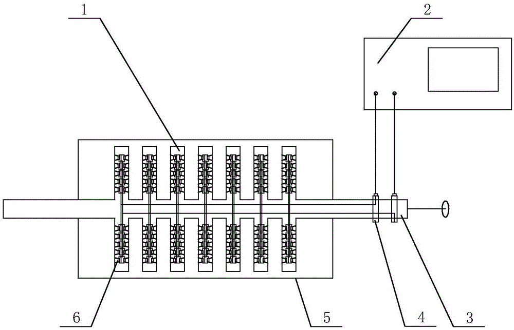
[0021] Such as figure 1 As shown, the built-in ultrasonic stirring crystallizer of the present invention includes a cylinder body 5, the central axis of the cylinder body 5 is provided with a hollow shaft 3, the two ends of the hollow shaft 3 pass through the cylinder body 5, two of the hollow shaft 3 A plurality of vibrator groups 1 are provided on the side, a plurality of ultrasonic vibrators 6 are provided inside the vibrator group 1, and a brush group 4 is provided at one end of the hollow shaft 3, and one end of the brush group 4 is connected to the ultrasonic vibrator 6 through a wire, The other end is connected to the ultrasonic generator 2 through a wire.

[0022] Among them, the vibrator group 1 is evenly distributed on both sides of the hollow shaft 3; the wire between the brush group 4 and the ultrasonic vibrator 6 is located inside the hollow shaft 3, and the hollow shaft 3 can realize forward and reverse rotation; The outer side is wrapped with an anti-corrosion lay...

Embodiment 2

[0024] On the basis of Embodiment 1, the outer side of the vibrator group 1 can also be treated with anti-corrosion materials, which mainly play a role of anti-corrosion.

[0025] The specific use process of the present invention:

[0026] When in use, the ultrasonic vibrator 6 inside the crystallizer is powered by the brush set 4 and the wire, and the ultrasonic wave generated by the ultrasonic vibrator 6 allows the supersaturated liquid inside the cylinder 5 to be released quickly and uniformly, and the solution in the cylinder 5 is supersaturated The degree can be a cold or heat source from the inside of the cylinder 5, such as an electric heating rod inserted into the cylinder, or a cold or heat source from the outside, such as making a jacket on the equipment housing and passing the heat into the jacket. Steam or circulating cooling water; the hollow shaft 3 can rotate clockwise or counterclockwise to drive the vibrator group 1 to rotate in the cylinder 5, which plays a role o...


PUM


Abstract

The invention relates to a crystallizer, in particular relates to a built-in ultrasonic stirring crystallizer. The built-in ultrasonic stirring crystallizer comprises a barrel body, wherein a hollow shaft is arranged in the position of a central axis of the barrel body; two ends of the hollow shaft penetrate through the barrel body; two sides of the hollow shaft are provided with multiple vibrator groups; multiple ultrasonic vibrators are arranged in the vibrator groups; one end of the hollow shaft is provided with an electric brush group; one end of the electric brush group is connected with the ultrasonic vibrators through wires, and the other end of the electric brush group is connected with an ultrasonic generator through a wire. According to the built-in ultrasonic stirring crystallizer disclosed by the invention, the built-in ultrasonic stirring crystallizer can be prevented from scaling to a certain degree, the unsaturation degree of a solution can be rapidly released by ultrasonic waves, uniform growth of crystals is promoted, materials are prevented from concentrating and crystallizing on a heat exchange interface, and dirt on the scaled heat exchange interface can be removed by the ultrasonic waves; the ultrasonic vibrators are enough close to the heat exchange interface, a using effect of removing the dirt is ensured, and the energy consumption is lower.

Description

Technical field [0001] The invention relates to a crystallizer, in particular to a built-in ultrasonic stirring crystallizer. Background technique [0002] Traditional crystallization equipment is prone to wall hanging during the crystallization process, and problems such as scaling and blockage at the heat exchange interface are prone to occur. The existing ultrasonic descaling equipment cannot penetrate deep into the solution, and has high energy consumption and cannot promote uniform crystals. It is easy to crystallize at the heat exchange interface. Summary of the invention [0003] In order to solve the deficiencies in the above technical problems, the purpose of the present invention is to provide a built-in ultrasonic stirring crystallizer with low energy consumption, which can effectively prevent the crystallization of materials at the heat exchange interface and prevent fouling. [0004] The technical solutions adopted by the present invention to solve its technical proble...

Claims


Application Information

Patent Timeline
IPC IPC(8): B01D9/02B01J19/10
CPCB01D9/0081B01D2009/0086
Inventor 徐翔
Owner 徐翔
Why Eureka
Try Eureka