Al technical title is built by PatSnap Al team. It summarizes the technical point description of the patent document.
A workbench and copper strip technology, applied in the field of punching machines, can solve the problems of being unsuitable for large-scale production, heavy workload of workers, and low degree of automation, achieving huge economic and social benefits, simple structure, and labor-saving effects
Active Publication Date: 2016-05-11
TAIZHOU YOURUN ELECTRONICS
View PDF7 Cites 3 Cited by
Summary
Abstract
Description
Claims
Application Information
AI Technical Summary
This helps you quickly interpret patents by identifying the three key elements:
Problems solved by technology
Method used
Benefits of technology
Problems solved by technology
The above-mentioned stamping technology is relatively cumbersome, with low degree of automation, time-consuming and labor-intensive, and the workload of workers is heavy. Many workers need to be hired, and the cost is high.
And stamping speed is slow, work efficiency is low, not suitable for mass production
Method used
Image
Click on the blue label to locate the original text in one second.
Reading with bidirectional positioning of images and text.
Examples
Embodiment Construction
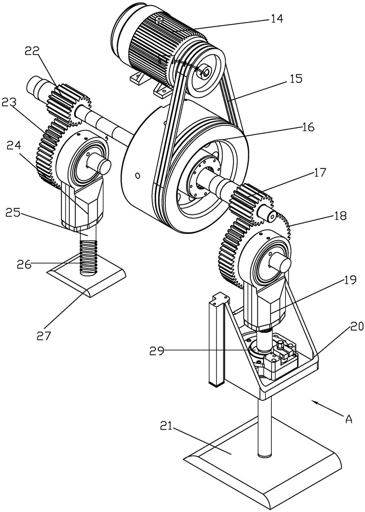
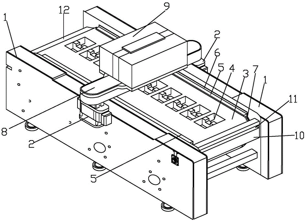
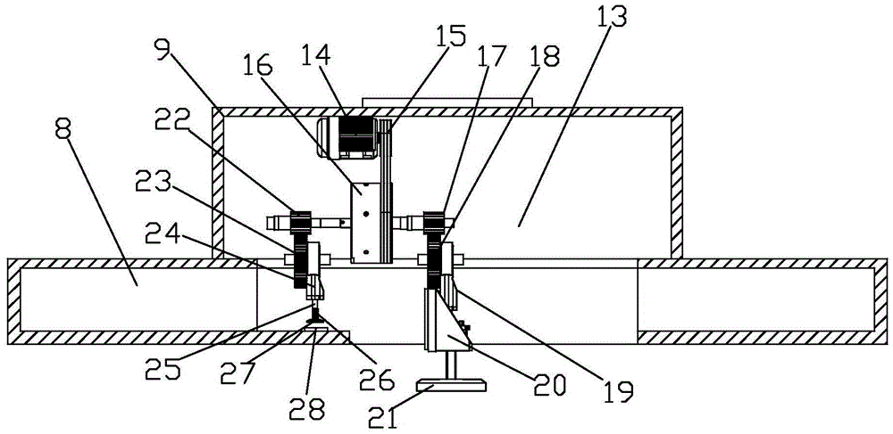
[0028] Such as Figure 1 to Figure 6 As shown, a continuous copper strip stamping workbench includes a frame 1, an upper mold 21, a lower mold 4 and a lifting mechanism. The frame 1 is composed of the left frame 1 and the right frame 1. The frame 1 is 10m long and 0.95m wide. The frame 1 is made of steel and has a firm structure. A guide belt 3 is connected between the left frame 1 and the right rack 1, and the guide belt 3 is laid with guide belt adhesive 7 on the left and right sides. The guide belt adhesive 7 is viscous and can stick to the copper belt so that it The guide belt 3 moves at a constant speed, and continuous production is realized on this basis. The guide belt glue 7 is easy to obtain materials and low in cost; the guide belt 3 is fixed with a lower mold 4, and the lower molds 4 are uniformly arranged at an interval of 0.25m; each lower mold 4 The bottom of each is equipped with a hydraulic cylinder 30, and the hydraulic cylinder 30 corresponds to the lower mo...
PUM
Abstract
The invention discloses a continuous copper strip stamping worktable. The continuous copper strip stamping worktable comprises frames, an upper mold, a lower mold and lifting mechanisms; a guide strip is connected between the frames; the lower mold is fixed in the guide strip; the bottom of the lower mold is connected with a hydraulic oil cylinder; a cross beam is mounted on the frames; a control box is mounted at the upper end of the cross beam; the lifting mechanisms are mounted in the cross beam and the control box; the lifting mechanisms include driving devices, first gear shafts, second gear shafts, first eccentric gears, first lifting links, second eccentric gears, second lifting links and elastic guide columns; a guide strip switch is arranged at the lower end in the cross beam; and the elastic guide columns are matched with the guide strip switch. The continuous copper strip stamping worktable introduces the guide strip structure based on a traditional stamping forming technology, installs the lower mold on the guide strip, conveys the lower mold at constant speed by dint of the guide strip, and stamps the lower mold by the upper mold in the conveying process to realize automatic continuous production. The continuous copper strip stamping worktable saves both time and labors, reduces the cost, is fast in stamping speed, and obviously enhances the working efficiency.
Description
technical field [0001] The invention relates to a stamping machine, in particular to a continuous copper strip stamping workbench. Background technique [0002] Copper strip is a kind of metal component, the product specifications are (0.1~3)×(50~250)mm copper strip products in various states, mainly used in the production of electrical components, lamp holders, battery caps, buttons, seals, connectors , mainly used as electrical, thermal, and corrosion-resistant equipment. Such as electrical components, switches, gaskets, gaskets, electric vacuum devices, radiators, conductive base materials, and automotive water tanks, heat sinks, cylinder plates and other parts. [0003] The copper strip is processed into various parts, which requires the use of stamping forming technology; the existing stamping forming technology is: first, the worker adjusts the mold on the punching machine, puts the adjusted mold into the press, and uses the press to press the copper strip. into vari...
Claims
Application Information
Patent Timeline
Application Date:The date an application was filed.
Publication Date:The date a patent or application was officially published.
First Publication Date:The earliest publication date of a patent with the same application number.
Issue Date:Publication date of the patent grant document.
PCT Entry Date:The Entry date of PCT National Phase.
Estimated Expiry Date:The statutory expiry date of a patent right according to the Patent Law, and it is the longest term of protection that the patent right can achieve without the termination of the patent right due to other reasons(Term extension factor has been taken into account ).
Invalid Date:Actual expiry date is based on effective date or publication date of legal transaction data of invalid patent.