Spot welding machine

A technology of spot welding machine and welding host, which is applied in the direction of welding equipment, welding equipment, resistance welding equipment, etc., and can solve problems such as poor spot welding quality, product scrapping, and affecting the effect of surfacing welding

Inactive Publication Date: 2016-05-11
SEED TECH CORP LTD
View PDF13 Cites 2 Cited by
  • Summary
  • Abstract
  • Description
  • Claims
  • Application Information

AI Technical Summary

Problems solved by technology

Therefore, a lot of time and manpower are wasted in the process of adjusting the working position; at the same time, due to the frequent replacement of electrodes, it is easy to cause errors, resulting in poor spot welding quality, affecting the effect of surfacing welding, and even causing product scrapping, resulting in cost waste and work efficiency. extremely low

Method used


Image

  • Spot welding machine
  • Spot welding machine

Examples


Embodiment Construction

[0024] The core of the present invention is to provide a spot welding machine, which effectively improves the working efficiency of the spot welding machine.

[0025] The following will clearly and completely describe the technical solutions in the embodiments of the present invention with reference to the accompanying drawings in the embodiments of the present invention. Obviously, the described embodiments are only some, not all, embodiments of the present invention. Based on the embodiments of the present invention, all other embodiments obtained by persons of ordinary skill in the art without making creative efforts belong to the protection scope of the present invention.

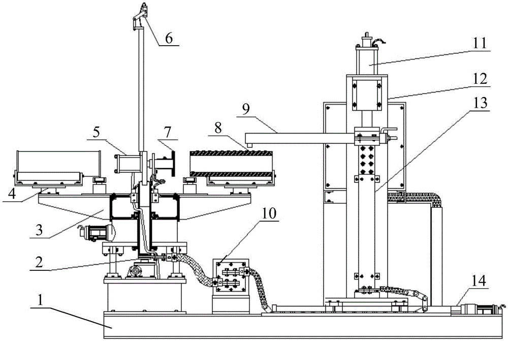
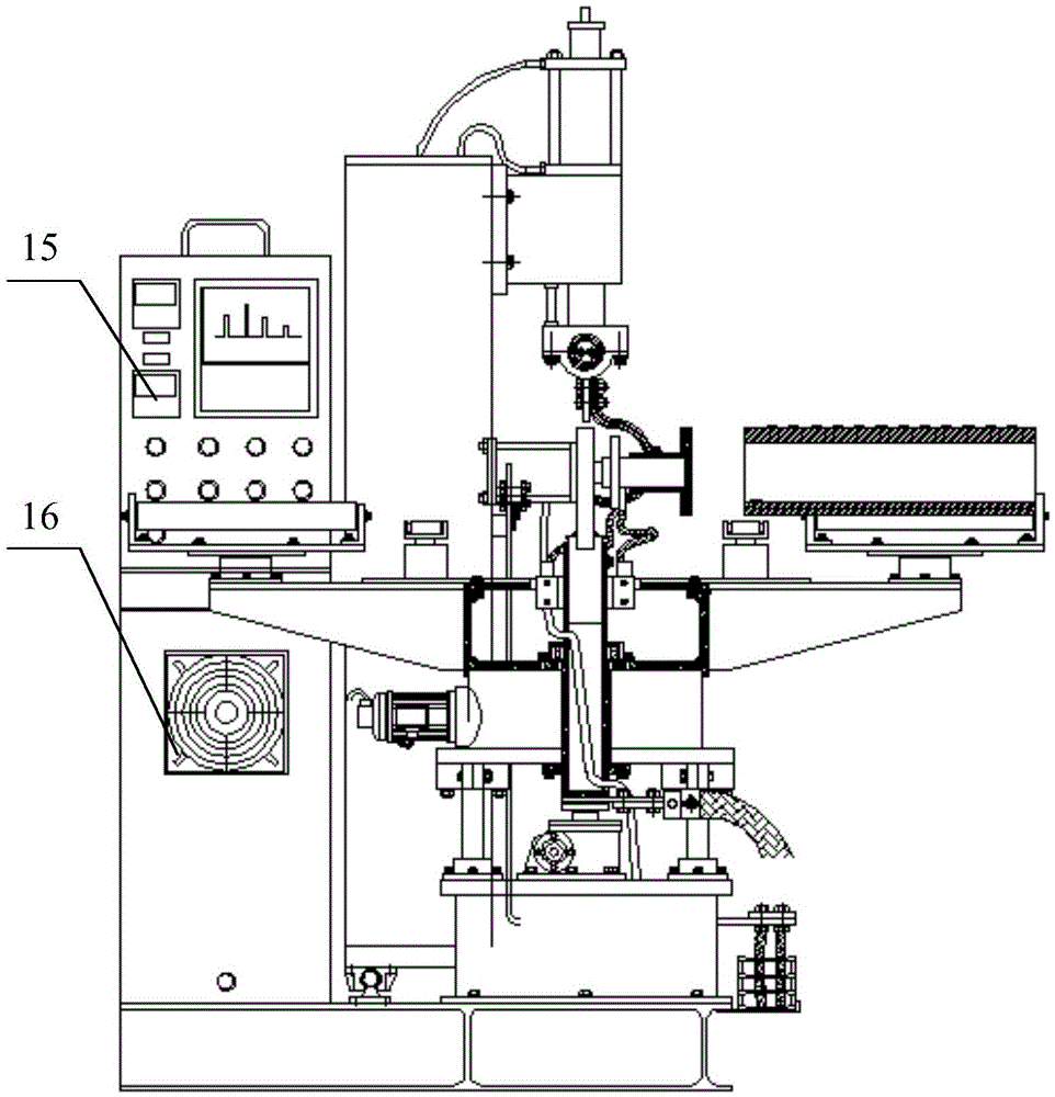
[0026] Please refer to figure 1 and figure 2 , figure 1 It is a schematic structural view of a spot welding machine provided by a specific embodiment of the present invention; figure 2 for figure 1 another view of .

[0027] In a specific embodiment, the spot welding machine provided by the prese...


PUM


Abstract

The invention discloses a spot welding machine. The spot welding machine comprises a platform, a welding main unit and a driving device, wherein the platform is provided with stations (4), an electrode (9) is installed on the welding main unit, and the driving device is used for driving the welding main unit to operate. The welding main unit is installed on a traveling mechanism (14) which can move in the axis direction of a workpiece (8). The working efficiency of the spot welding machine is effectively improved.

Description

technical field [0001] The invention relates to the technical field of spot welding, in particular to a spot welding machine. Background technique [0002] Hard facing technology is to use the well-known methods of thermal spraying, spray welding, surfacing and sintering to apply hard facing materials to the most common working surfaces of metal parts by welding, and use hard facing technology to coat different materials. With hard surface materials, the part can be very wear-resistant, impact-resistant, and corrosion-resistant, such as tungsten carbide radial bearings, stabilizers, etc. At present, the main way to prepare products with the above properties is to first fix the cemented carbide alloy block on the surface of the metal substrate, and then adopt some wear-resistant additives or solder to the metal substrate, cemented carbide Blocks, wear-resistant additives or solder are combined to form a composite hard surface material, so that the wear resistance and corrosi...

Claims


Application Information

Patent Timeline
Patent Type & Authority Applications(China)
IPC IPC(8): B23K11/11B23K37/02
CPCB23K11/115B23K37/02
Inventor 张力平王玉鹏徐跃华
Owner SEED TECH CORP LTD
Why Eureka
Try Eureka