Booster system and low noise control method

A supercharger and compressor technology, applied in pump control, machine/engine, components of pumping devices for elastic fluids, etc., can solve the problem of being unable to reduce low- and medium-frequency noise and high-frequency noise at the same time, and achieve improvement Passive acoustic properties, low cost, low cost effect

Active Publication Date: 2016-05-11
WEICHAI POWER CO LTD
View PDF7 Cites 10 Cited by
  • Summary
  • Abstract
  • Description
  • Claims
  • Application Information

AI Technical Summary

Problems solved by technology

[0009] The technical problem to be solved by the present invention is to provide a supercharger system and a low-noise control method, improve the structure of the supercharger, cut off the noise from the soun...

Method used


Image

  • Booster system and low noise control method
  • Booster system and low noise control method

Examples


Embodiment 1

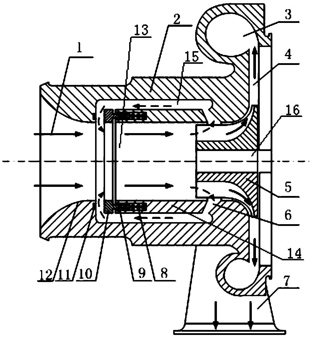
[0037] Such as figure 1 As shown, a supercharger system provided in this embodiment includes a compressor housing 2 and a rotor, the rotor is fixed in the compressor housing 2 through a rotating shaft 16, and the space between the compressor housing 2 and the rotor blades 5 of the rotor is There is an annular gap, the compressor housing 2 is provided with a compressor inner wall 14, the compressor inner wall 14 encloses an intake cavity 13, and the intake cavity 13 communicates with the annular gap; the compressor housing 2 and the compressor inner wall 14 Form the airflow channel 15 that is arranged along the direction of the airflow in the intake cavity 13 between, the inlet of the airflow channel 15 communicates with the annular gap, the outlet of the airflow channel 15 communicates with the air inlet of the intake cavity 13; on the compressor inner wall 14 There is an actuator for allowing or preventing the airflow from flowing through the outlet of the airflow channel 15,...

Embodiment 2

[0045] A low-noise control method for a supercharger system provided in this embodiment includes the following steps:

[0046] S1, the air intake cavity 13 is arranged in the compressor casing, the noise reduction ring 12 is communicated with the air inlet of the intake cavity 13, and the middle and low frequency noise when the air flow enters the intake cavity 13 is reduced through the noise reduction ring 12;

[0047] S2. The air intake cavity 13 is formed by the inner wall 14 of the compressor. An airflow channel 15 is formed between the inner wall 14 of the compressor and the compressor housing 2. The inlet of the airflow channel 15 is provided with a flow widening groove 6, through which the air flow is reduced. Medium and low frequency noise when entering the airflow channel 15; among them, the flow widening groove 6 plays the role of widening the flow rate, and when the compressor has a small flow rate and high pressure ratio, it is farther away from the surge line, ther...


PUM


Abstract

The invention relates to the technical field of engines, in particular to a booster system and a low noise control method. An annular clearance is formed between a compressor shell of the system and a rotor vane of a rotor, a compressor inner wall is arranged in the compressor shell, an air intake cavity is formed by encircling of the compressor inner wall, the air intake cavity communicates with the annular clearance; an airflow passage arranged along the direction of air flow in the air intake cavity is formed between the compressor shell and the compressor inner wall; the compressor inner wall is provided with an executing mechanism used for allowing the air flow to pass through an outlet of the airflow passage or preventing the airflow from flowing through the outlet of the airflow passage. According to the low noise control method, a noise reduction ring and a flow widening slot are used for jointly changing low frequency noise and lowering high frequency noise via the executing mechanism. According to the booster system and the low noise control method, structure improvement can be achieved on a booster, noise isolation can be carried out on a sound wave transmission path, and the system and the method are applicable to all runoff type boosters, thus solving the problem of the prior art that low frequency noise and high frequency noise cannot be lowered at the same time.

Description

technical field [0001] The invention relates to the technical field of engines, in particular to a supercharger system and a low-noise control method, and more particularly to a supercharger system and a low-noise control method capable of simultaneously reducing middle-low frequency noise and high-frequency noise. Background technique [0002] With the increasingly stringent requirements for carbon emission restrictions, supercharging technology has become an inevitable choice for the development of engine technology. As the pressure ratio of the supercharger has gradually increased in recent years, people's requirements for the comfort of the engine have also begun to increase, resulting in the noise problem of the supercharger becoming an issue that manufacturers and users are paying more and more attention to. [0003] At present, the most common means to directly solve the noise problem of a flow-type exhaust gas turbocharger is to use a muffler ring and / or a flow widen...

Claims


Application Information

Patent Timeline
IPC IPC(8): F04D17/10F04D29/66F04D29/42F04D27/00
CPCF04D17/10F04D27/009F04D29/4206F04D29/4213F04D29/663F04D29/667
Inventor 张杰黄国龙文志永
Owner WEICHAI POWER CO LTD
Why Eureka
Try Eureka