Modified coherence peak demodulation method for fiber end face detection

A technology of optical fiber end face and demodulation method, which is applied in the direction of adopting optical devices, measuring devices, instruments, etc., can solve the problems of large amount of calculation, affecting the positioning of zero-order fringes, random errors, etc., and achieve fast calculation speed, high precision, and reduced Effect of altitude measurement error

Inactive Publication Date: 2016-05-11
BEIHANG UNIV
View PDF3 Cites 13 Cited by
  • Summary
  • Abstract
  • Description
  • Claims
  • Application Information

AI Technical Summary

Problems solved by technology

However, when using the traditional Carré phase-shift algorithm to extract the phase, it is necessary to unwrap the phase, which requires a large amount of calculation and a relatively long time.
In the actually detected interf

Method used


Image

  • Modified coherence peak demodulation method for fiber end face detection
  • Modified coherence peak demodulation method for fiber end face detection
  • Modified coherence peak demodulation method for fiber end face detection

Examples


Embodiment Construction

[0017] The present invention will be described in detail below in conjunction with the drawings and embodiments.

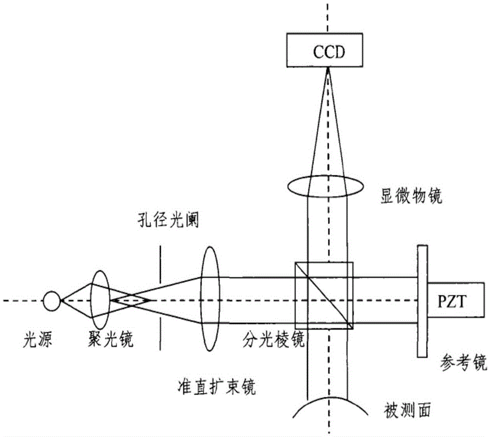
[0018] Such as figure 1 Shown is a schematic diagram of the principle of the fiber end face measurement system. The light source passes through the condenser, aperture diaphragm, and collimating beam expander to the beam splitter prism. Part of the light will reach the end face of the fiber under test, and the other part will reach the reference mirror. The micro objective lens finally reaches the CCD imaging. When interference occurs, interference fringes generated by light of each wavelength are superimposed to form white light interference fringes. When the piezoelectric ceramic (PZT) phase shifter drives the standard surface to move, the interference fringes will change.

[0019] The optical fiber end-face measuring instrument measures the three-dimensional topography, and obtains the relative height value of the object surface according to the light intensity val...


PUM


Abstract

The invention discloses a modified coherence peak demodulation method for fiber end face detection, and belongs to the technical field of a fiber end face measuring instrument. The demodulation method comprises quickly limiting phase extraction in a zero order stripe through a modified extremum method, and reducing the random error caused by environment disturbance and CCD shot noise; and performing phase correction for the extracted light intensity maximum based on a Carre phase shift algorithm, and eliminating the influence of the linear phase shift error on the fiber end face height value. During the process for calculating the fiber end face height value, the modified coherence peak demodulation method has no demand for performing phase unwrapping operation, thus improving the calculating speed, and has the advantages of being insensitive to the linear error Epsilon of a phase shifter, and being high in precision.

Description

Technical field [0001] The invention relates to an improved coherent peak demodulation method suitable for optical fiber endface detection, and belongs to the technical field of optical fiber endface measuring instruments. Background technique [0002] The fiber end-face measuring instrument is based on the principle of white light interference, which uses phase shift to realize the change of the interference fringes of the fiber end face. The fiber end face tester can accurately and quickly measure the surface topography of the fiber without contact. As the transmission medium of optical signals, the shape of the optical fiber end face directly affects the transmission performance of the optical signal in the optical fiber. Therefore, the measurement of the end face shape of the optical fiber is very important in the optical fiber sensing and transmission. Since the fiber end-face measuring instrument can meet the online testing requirements of the fiber in the production and a...

Claims


Application Information

Patent Timeline
IPC IPC(8): G01B11/24G01B11/02
CPCG01B11/02G01B11/2441
Inventor 谭朦曦李慧鹏高爽朱伟伟宋凝芳李皎
Owner BEIHANG UNIV
Why Eureka
Try Eureka