Smart meter RTC timing precision correction circuit and method thereof

A technology for smart meters and correction circuits, applied in the direction of temporarily changing the number of pulses per unit time, etc., can solve problems such as low compensation efficiency, occupying MCU, and a large number of caches, and achieves low power consumption, low power consumption, and reduced impact. Effect

Active Publication Date: 2016-05-11
CRM ICBG (WUXI) CO LTD
View PDF6 Cites 17 Cited by
  • Summary
  • Abstract
  • Description
  • Claims
  • Application Information

AI Technical Summary

Problems solved by technology

In fact, in order to obtain a uniform pulse per second, this method requires a large amount of buffer memory, and occupies the MCU, which is costly and low in compensation efficiency.

Method used


Image

  • Smart meter RTC timing precision correction circuit and method thereof
  • Smart meter RTC timing precision correction circuit and method thereof
  • Smart meter RTC timing precision correction circuit and method thereof

Examples


Embodiment 1

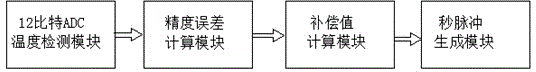
[0028] Embodiment 1: The curve fitting in this embodiment adopts a cubic curve, the horizontal axis of the curve represents the temperature, and the vertical axis represents the frequency of the crystal oscillator. The working process of generating the second pulse in the present embodiment is according to the appended image 3 shown in the block diagram to complete.

[0029] Method steps: (1) Firstly, the crystal oscillators are screened in batches, specifically, the quadratic coefficients with the opening upward The error is controlled within ± The crystal oscillators are screened out in batches; (2) Then, the crystal oscillators screened in batches are fitted with cubic curves. Specifically, Matlab function software can be used to operate. After fitting, the results are obtained according to the functions of the software. , , T 0 value, and write this value into the crystal oscillator error calculation circuit; (3) Then measure the crystal oscillator offest value, and...

Embodiment 2

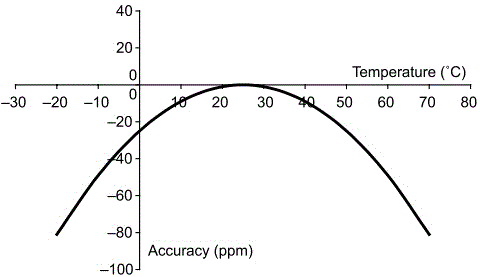
[0031] Embodiment two: the curve fitting in the present embodiment adopts quadratic curve, and the curve after its fitting is as attached figure 2 As shown, the horizontal axis of the curve represents the temperature, and the vertical axis represents the crystal oscillator frequency. The working process of generating the second pulse in the present embodiment is according to the appended image 3 shown in the block diagram to complete. Because what this embodiment adopts is the fitting of quadratic curve, adopt Matlab function software to operate, can only draw according to the function of software after fitting , T 0 value, at this time, only the crystal oscillator error formula middle Substituting the value into "0" will give the crystal oscillator error value. Except for step (2), the steps in this embodiment are basically the same as those in Embodiment 1, and the same content will not be repeated here.

[0032] Although the accuracy of the cubic curve is higher,...


PUM


Abstract

The invention relates to the field of smart meters, and specifically relates to a smart meter RTC timing precision correction circuit and a method thereof. The circuit comprises a 12-bit ADC temperature detection module, a precision error calculation module, a compensation value calculation module and a second pulse generation module. The method comprises the following steps: screening out a crystal oscillator; fitting a curve; calculating the error of the crystal oscillator; calculating the compensation value; working out the pulse compensation cycle according to the compensation value; defining the accumulative error; and adjusting a counter according to the accumulative error and the pulse number corresponding to the compensation cycle, wherein the counter stops counting for one beat if the error of the crystal oscillator is positive and the clock frequency is quicker, and the counter adds 2 to the number if the error of the crystal oscillator is negative and the clock frequency is slower. Through the correction method of the invention, a precise second pulse can be obtained, there is no need for a large amount of stored data, the memory is saved, power consumption is reduced, the timing precision is improved, and the influence of temperature on the timing precision is reduced.

Description

technical field [0001] The invention relates to the technical field of smart meters, in particular to a circuit and method for correcting RTC timing accuracy in smart meters. Background technique [0002] As we all know, a smart meter is an intelligent terminal of a smart grid. It is no longer an electric energy meter in the traditional sense. In addition to the basic power consumption measurement function of a traditional electric energy meter, in order to adapt to the use of smart grid and new energy, it also It has intelligent functions such as two-way multi-rate metering function, user-end control function, two-way data communication function of multiple data transmission modes, and anti-stealing function. Smart meters represent the future energy-saving smart grid end-user intelligent terminal Direction of development. Smart watt-hour meter is a new type of watt-hour meter. Compared with ordinary watt-hour meters in the past, in addition to basic metering functions, sma...

Claims


Application Information

Patent Timeline
Patent Type & Authority Applications(China)
IPC IPC(8): G04G5/02
Inventor 吕超英周璐梅平陈富涛
Owner CRM ICBG (WUXI) CO LTD
Why Eureka
Try Eureka