

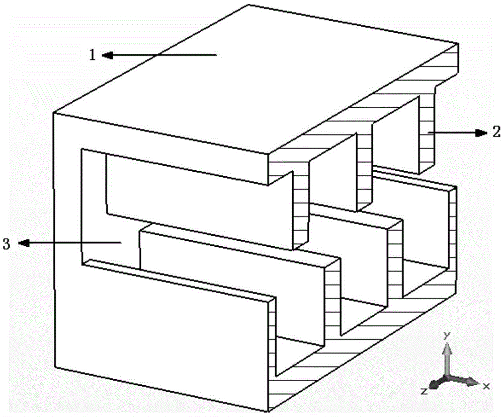
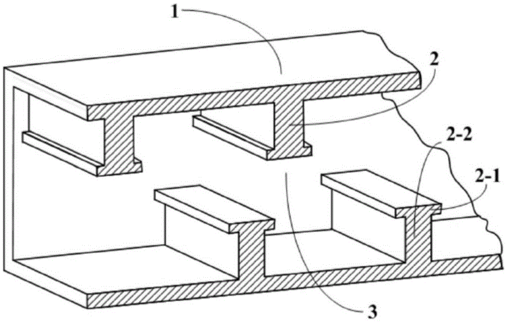
Half-cycle staggered cosine end plane gate slow wave structure
A slow-wave structure and cosine technology, applied in the field of microwave vacuum electronic devices, can solve the problems of large high-frequency loss and increased high-frequency loss, and achieve the effects of reducing high-frequency loss, increasing cold bandwidth, and improving dispersion characteristics
- Summary
- Abstract
- Description
- Claims
- Application Information
AI Technical Summary
Problems solved by technology
Method used
Image

Examples
example 1
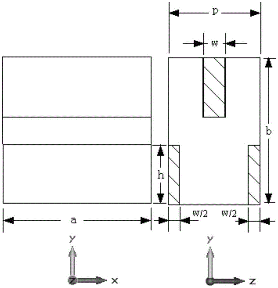
[0031] A half-period interlaced cosine end-face grating slow-wave structure according to the present invention, the specific scheme structure size is as follows, the unit is mm: rectangular waveguide wide side length a=0.68, waveguide narrow side length b=0.64, geometric period p=0.4, cosine The grid body width w=0.1, the grid body height h=0.26, and the amplitude Ac of the cosine profile is 0.005. Use 3D electromagnetic software to simulate the slow wave structure of this example, and calculate the dispersion curve, axial coupling impedance and high frequency loss. The simulation results are as follows Image 6 , as shown in 7 and 8.
example 2
[0033] A half-period interlaced cosine end-face grating slow-wave structure according to the present invention, the specific scheme structure size is as follows, the unit is mm: waveguide wide side length a=0.68, waveguide narrow side length b=0.64, geometric period p=0.4, cosine grating Body width w=0.1, grid body height h=0.26, amplitude Ac of cosine profile is 0.01. Utilize three-dimensional electromagnetic software to simulate a half-period interlaced cosine face grating slow-wave structure of the present invention, and calculate the dispersion curve, axial coupling impedance and high-frequency loss, and the simulation results are as follows Image 6 , as shown in 7 and 8.
[0034] Image 6 The simulation results of the dispersion curve show that, compared with the rectangular end-face half-period interleaved double-grid slow-wave structure, the lower cut-off frequency and the upper cut-off frequency of the fundamental wave of the half-period interleaved cosine end-face d...
PUM
 Abstract
Description
Claims
Application Information