Electronic component mounting substrate, method for manufacturing the electronic component mounting substrate, motor and air-conditioning apparatus,

A technology for electronic components and mounting substrates. It is used in the manufacture of motor generators, electrical components, and printed circuit manufacturing. It can solve problems such as poor operation of electronic components, increased residual stress, and failure of electronic circuits to operate normally.

Active Publication Date: 2016-05-11
MITSUBISHI ELECTRIC CORP
View PDF5 Cites 2 Cited by
  • Summary
  • Abstract
  • Description
  • Claims
  • Application Information

AI Technical Summary

Problems solved by technology

[0004] However, in the case of the structure of Patent Document 1, there is a problem that water infiltrates from the gap formed at the interface between the lead wire and the mold that resin-seals the lead wire and the substrate, causing malfunction of the electronic components on the substrate.
For example, when an electronic component mounting substrate is used for a motor, there is a problem that the electronic circuit on the substrate cannot operate normally due to a short circuit of the power supply, and the motor cannot be controlled.
As a result, there is also a problem that the motor cannot be controlled normally
[0006] In addition, in the case of using a liquid coating agent, the film thickness cannot be made uniform by surface tension
For example, there is a problem that the film thickness becomes extremely thin at the edge of the element, and the residual stress increases due to the non-uniformity of the film thickness, and if further stress is applied from the outside, cracks are likely to occur

Method used


Image

  • Electronic component mounting substrate, method for manufacturing the electronic component mounting substrate, motor and air-conditioning apparatus,
  • Electronic component mounting substrate, method for manufacturing the electronic component mounting substrate, motor and air-conditioning apparatus,
  • Electronic component mounting substrate, method for manufacturing the electronic component mounting substrate, motor and air-conditioning apparatus,

Examples


Embodiment approach 1

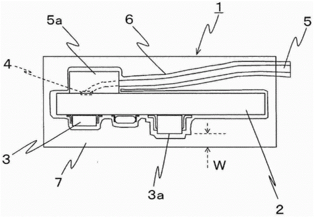
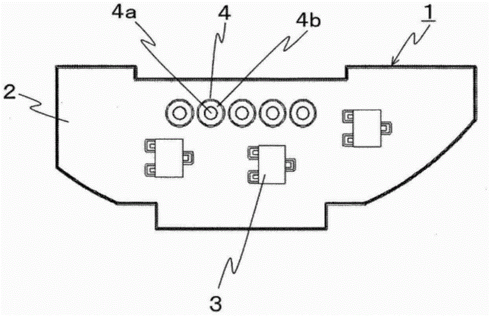
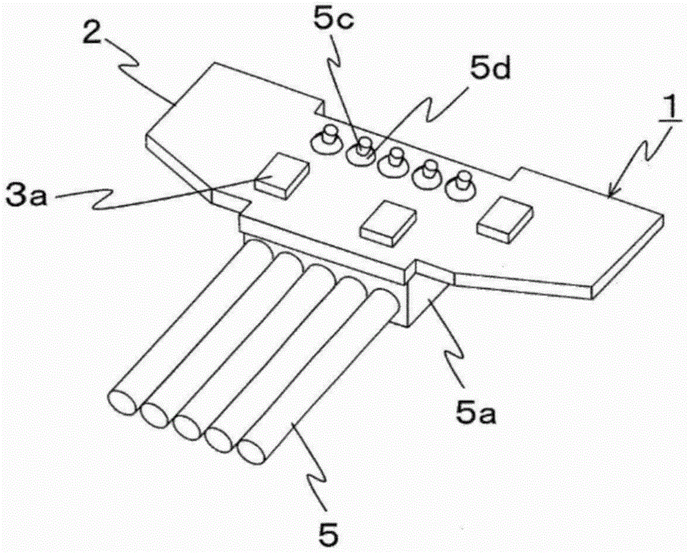
[0043] figure 1 It is a schematic cross-sectional view of the electronic component mounting board 1 of this embodiment. At least one electronic component 3 is mounted on the surface of the plate-shaped substrate 2 . Electronic component 3 is mounted on one or both surfaces of substrate 2 . exist Figure 1 ~ Figure 3 In the example of , the electronic component 3 is mounted on only one side of the substrate 2 . Hereinafter, for convenience of description, the surface on which the electronic component 3 is mounted is referred to as a component mounting surface. Electronic components 3 can be connected to each other by patterned conductive circuit wiring (not shown) on the surface of the substrate 2 to form an electronic circuit (not shown). The electrode portion 4 is electrically connected to the electronic component 3 directly or via the electronic circuit. A through hole 4 a penetrating the substrate 2 is formed in the center of the electrode portion 4 , and a metal foil ...

Embodiment approach 2

[0067] Figure 13 It is a figure which shows the air conditioner 40 provided with the electric motor 20. The air conditioner 40 includes an outdoor unit 41 and an indoor unit 42 connected to the outdoor unit 41 . The outdoor unit 41 and the indoor unit 42 include an evaporator, a condenser, a compressor, and an expansion mechanism (not shown), and constitute a refrigeration cycle system with these components. The outdoor unit 41 includes a blower 43 . The air blower 43 is provided with the electric motor 20 in Embodiment 1.

[0068] Since the air conditioner 40 of the present embodiment includes the motor 20, it can be operated normally even when the air conditioner 40 is used in a high-humidity environment. In addition, the motor 20 can be used not only for the air conditioner 40 but also for various devices such as a heat pump device (not shown), and the same effect can be obtained.


PUM


Abstract

An electronic component mounting substrate includes an electronic component mounted on a surface of a substrate, an electrode portion disposed on the surface of the substrate and electrically connected to the electronic component, a lead wire connected to the electrode portion, and an encapsulation resin configured to encapsulate a part of the lead wire, the electronic component, and the electrode portion. A surface of at least the part of the lead wire encapsulated by the encapsulation resin and the surface of the substrate are coated with a deposited film.

Description

technical field [0001] The present invention relates to an electronic component mounting substrate, a motor including the electronic component mounting substrate, an air conditioner including the electric motor, and a method for manufacturing the electronic component mounting substrate. Background technique [0002] Conventionally, when there is a possibility that a substrate on which an electronic component is mounted may be exposed to water, a resin coating is applied to the surface of the substrate in order to prevent water and moisture. For example, in Patent Document 1, in the region of the substrate surface, a resin is applied to the region where the connecting portion of the wire is formed, and the coating is provided on the region (for example, paragraph 0044). In addition, resin sealing is performed on the substrate with the coating applied to a part of the surface by insert molding (for example, paragraph 0049, FIG. 5 ). It is intended to improve waterproofness by...

Claims


Application Information

Patent Timeline
Patent Type & Authority Applications(China)
IPC IPC(8): H02K5/22H01L21/60H01L23/02F25B49/00
CPCH01L23/3121H01L23/3135H01L2924/0002H02K5/08H02K5/225H02K15/12H02K11/33H01L2924/00H05K1/181H05K1/053H05K3/303H05K2201/1009H02K11/30H02K3/00
Inventor 松永训明
Owner MITSUBISHI ELECTRIC CORP
Why Eureka
Try Eureka