Method for determining movement tracks of industrial robot

A kind of robot motion and robot technology, applied in the direction of instruments, manipulators, manufacturing tools, etc., can solve the problems that cannot be widely used in the field of complex surface processing, and the working space of industrial robots is limited, so as to shorten the planning time and improve the work efficiency.

Active Publication Date: 2016-05-25
苏州瀚华智造智能技术有限公司
View PDF5 Cites 9 Cited by
  • Summary
  • Abstract
  • Description
  • Claims
  • Application Information

AI Technical Summary

Problems solved by technology

[0006] In view of the problems existing in the prior art, the embodiment of the present invention provides a method for determining the motion trajectory of an industrial robot, which is used to solve the problem in the prior art that the five-axis toolpath trajectory generated by CAM cannot be converted into a six-axis industrial robot. The six-axis tool path leads to the limited working space of industrial robots and cannot be widely used in the field of complex curved surface processing

Method used


Image

  • Method for determining movement tracks of industrial robot
  • Method for determining movement tracks of industrial robot
  • Method for determining movement tracks of industrial robot

Examples


Embodiment 1

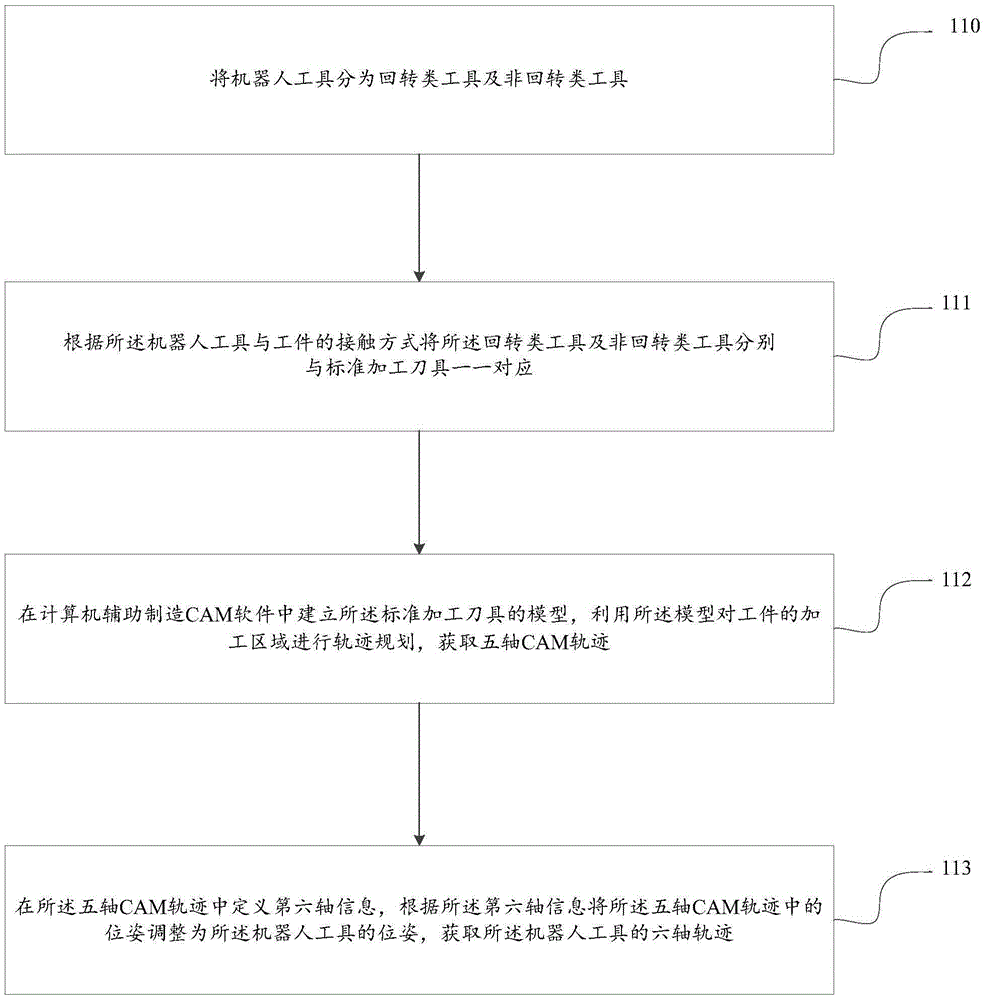
[0045] This embodiment provides a method for determining the trajectory of an industrial robot, such as figure 1 As shown, the method includes the following steps:

[0046] In step 110, the robot tools are divided into rotary tools and non-rotary tools.

[0047] In this step, the robot tools include: cutting tools, grinding tools, welding tools, spraying tools, laser forming tools, deburring tools, polishing tools and 3D printing tools; the rotary tools include: cylindrical tools, conical Tools and quasi-cylindrical tools. The non-rotating tools include: cuboid tools and the like.

[0048]Step 111 , according to the contact mode between the robot tool and the workpiece, the rotary tool and the non-rotary tool are respectively one-to-one corresponding to the standard machining tool.

[0049] In this step, after the robot tools are divided into rotary tools and non-rotary tools, the rotary tools and non-rotary tools are in one-to-one correspondence with standard machining too...

Embodiment 2

[0071] In actual application, when the workpiece is a curved surface of automobile glass, for the curved surface of automobile glass, a robot grinding tool is selected, such as Figure 12As shown, the tool is a rotary tool, and the contact mode with the curved surface of the automobile glass is side contact, so the flat bottom knife is selected as the standard tool for five-axis CAM trajectory generation.

[0072] First of all, in CAM software such as NX, the trajectory planning of the surface processing area of ​​the automobile glass is carried out. In the planning trajectory, a suitable flat-bottomed knife is selected as the machining tool for trajectory planning. The machining strategy is multi-axis variable contour milling, and the five-axis CAM trajectory, the trajectory such as Figure 13 shown.

[0073] Secondly, at first extract the tool location point and the tool axis vector data in the five-axis CAM track; Obtain ordered path point sequence P 1 , P 2 ......P i ....


PUM


Abstract

The invention provides a method for determining movement tracks of an industrial robot. The method includes: dividing robotic tools into rotational tools and non-rotational tools; enabling the rotational tools and the non-rotational tools to be in one-to-one correspondence with standard machining tools according to contact modes of the robotic tools and a workpiece; making models of the standard machining tools in CAM (computer-aided manufacturing) software, performing track planning on a machining area of the workpiece with the models, and acquiring a five-axis CAM track; defining information of a sixth axis in the five-axis CAM track, adjusting postures in the five-axis CAM track to be postures of the robotic tools, and acquiring six-axis tracks of the robotic tools. Plenty of five-axis CAM tracks can be transformed into stable and rational robot tracks, and accordingly the robot can be applied to the field of complex surface machining; time for robot track planning is shortened effectively, and working efficiency is improved; in addition, the tools in many machining fields such as cutting, polishing, welding, spraying and profiling are considered in the method, so that the method has general applicability.

Description

technical field [0001] The invention belongs to the technical field of industrial robot application, and in particular relates to a method for determining the motion trajectory of an industrial robot. Background technique [0002] Industrial robots are multi-joint manipulators or robots with multiple degrees of freedom for the industrial field. An industrial robot is a machine device that performs work automatically, and is a machine that realizes various functions by its own power and control capabilities. It can be commanded by humans or run according to pre-programmed programs. Modern industrial robots can also act according to the principles and programs formulated by artificial intelligence technology. [0003] Simple applications of industrial robots can be programmed by teaching. For complex applications, such as polishing, grinding, or welding of complex surfaces, the method of teaching programming cannot meet the processing requirements, and an offline programming ...

Claims


Application Information

Patent Timeline
Patent Type & Authority Applications(China)
IPC IPC(8): B25J9/16G06F17/50
CPCB25J9/1664G06F30/00
Inventor 颜昌亚赵云李振瀚
Owner 苏州瀚华智造智能技术有限公司
Why Eureka
Try Eureka