
Carbide drill and machining process thereof

A cemented carbide and drill technology, which is used in wood drilling tools, wood processing appliances, manufacturing tools, etc., can solve the problems of rough hole shape, easy blockage, poor chip removal performance, etc., to increase strength and impact resistance. , entry and exit for a brisk, beautifully shaped hole effect

Active Publication Date: 2016-05-25
ZHEJIANG LANGCHAO PRECISION MACHINERY
View PDF6 Cites 5 Cited by
  • Summary
  • Abstract
  • Description
  • Claims
  • Application Information

AI Technical Summary

Problems solved by technology

[0002] Carbide drill bits are mainly used for drilling in wooden furniture, such as keyhole processing on solid wood, veneered particleboard or MDF, drawer keyholes, etc.; currently the woodworking row drills on the market are mainly welded lug structures. Generally, the drilling speed should not be too fast, and the processed holes will be prone to chipping and clogging, and smoke and burns will easily occur during processing; when woodworking row drills are processed with CNC numerical control equipment at high speed, the surface of the workpiece after processing is easy to Burst edge, the processed hole shape is rough; the woodworking drill bit has poor wear resistance, poor chip removal performance and short service life when drilling solid wood veneer particleboard and MDF

Method used


Image

  • Carbide drill and machining process thereof
  • Carbide drill and machining process thereof
  • Carbide drill and machining process thereof

Examples


Embodiment Construction

[0029] Further explain below in conjunction with accompanying drawing:

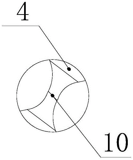
[0030] as attached Figure 1-6 Shown: the present invention comprises drill tip, cutter body, handle of a knife successively, wherein: described cutter body and handle of a knife are integrally formed, and described cutter body is provided with several helical grooves, and is set between the helical grooves and the horizontal plane. There is an included angle, the angle of the included angle is 10°-15°, the left end section of the drill tip is a tapered surface, and the end face of the cutter body close to the drill tip is the same taper as the left end section of the drill tip The inner cone angle of the cutter body is fixed by V-shaped butt welding on the end face of the drill tip. The drill tip includes a drill tip body and a drill tip tip. The surface shape of the drill tip body is It is W-shaped, the tip of the drill point is provided with a chisel edge, the drill point is provided with two cylindri...


PUM

PropertyMeasurementUnit
angleaaaaaaaaaa

Abstract

The invention relates to a carbide drill and a machining process thereof, and aims at providing a carbide drill with good wear resistance, good chip discharge performance and a long service life and a machining process thereof. The carbide drill comprises a drill tip, a tool body and a tool handle. The tool body and the tool handle are integrally formed, a plurality of spiral grooves are formed in the tool body, an included angle is formed between each spiral groove and the horizontal plane, and the included angle ranges from 10 degrees to 15 degrees. The left end section of the drill tip is a conical face, the end face, close to the drill tip, of the tool body has an inner conical angle with the taper identical to the taper of the left end section of the drill tip, and the end face, close to the drill tip, of the tool body is welded and fixed to the drill tip in a V-shaped butt welding mode. The drill tip comprises a drill tip body and a drill tip head, the surface of the drill tip body is in a W shape, a cross edge is arranged on the drill tip head, two cylindrical edge strips tangent to the outer circle of the drill tip are arranged on the drill tip, a marking edge parallel to the tool handle is arranged on the edge of the drill, and negative relief angle design is adopted in the marking edge. An adjusting screw capable of adjusting the length of the drill is arranged at the tail end of the tool handle.

Description

technical field [0001] The invention relates to a drill bit and its processing technology, in particular to a cemented carbide drill bit and its processing technology. Background technique [0002] Carbide drill bits are mainly used for drilling in wooden furniture, such as keyhole processing on solid wood, veneered particleboard or MDF, drawer keyholes, etc.; currently the woodworking row drills on the market are mainly welded lug structures. Generally, the drilling speed should not be too fast, and the processed holes will be prone to chipping and clogging, and smoke and burns will easily occur during processing; when woodworking row drills are processed with CNC numerical control equipment at high speed, the surface of the workpiece after processing is easy to The edge is burst, and the processed hole shape is rough; the woodworking drill bit has poor wear resistance, poor chip removal performance and short service life when drilling solid wood veneer particleboard and MD...

Claims


Application Information

Patent Timeline
Patent Type & Authority Applications(China)
IPC IPC(8): B27G15/00B23P15/32
CPCB23P15/32B27G15/00
Inventor 夏海甬林加清文志民郭艳美
Owner ZHEJIANG LANGCHAO PRECISION MACHINERY
Learn More