Nickel-base radiant tube and method for making the same

a technology of nickel-base and radiant tubes, which is applied in the direction of manufacturing tools, bends, lighting and heating apparatus, etc., can solve the problems of premature failure, high cost of upgrading old burners with a regenerative mechanism, and inability to achieve uniform temperature throughout the length of radiant tubes, etc., to reduce the amount of filler wire, reduce stress concentration, and reduce the effect of weld failur

Active Publication Date: 2011-12-29
ARCELORMITTAL INVESTIGACION Y DESARROLLO SL
View PDF2 Cites 28 Cited by
  • Summary
  • Abstract
  • Description
  • Claims
  • Application Information

AI Technical Summary

Benefits of technology

[0017]The method for making the nickel-base radiant tube according to the second aspect of the present invention has a number of advantages over the existing methods. Specifically, irrespective of the thicknesses of the straight tube section and elbow tube section, the slope of the sloped transition portion of the elbow tube section reduces the stress concentration during the welding operation, during service and reduces weld failures. Moreover, the weld joint, being away from the region of thickness change, will reduce the amount of filler wire needed and reduce cost. Furthermore, the weld joint according to the present invention eliminates welding of tube sections of different thicknesses...

Problems solved by technology

In reality, achieving uniform temperature throughout the length of the radiant tube is not practical.
There are regions with high temperature called hot spots, and at these hot spots the designed temperature may exceed and lead to a premature failure.
Upgrading old burners with a regenerative mechanism is an expensive task; therefore highly alloyed tubes are used as a counter measure.
However, there are occasions of tube failures associated with poor welds.
Some of the radiant tubes were found to fail prematurely within one year after installation.
Due to mismatch...

Method used


Image

  • Nickel-base radiant tube and method for making the same
  • Nickel-base radiant tube and method for making the same
  • Nickel-base radiant tube and method for making the same

Examples


Embodiment Construction

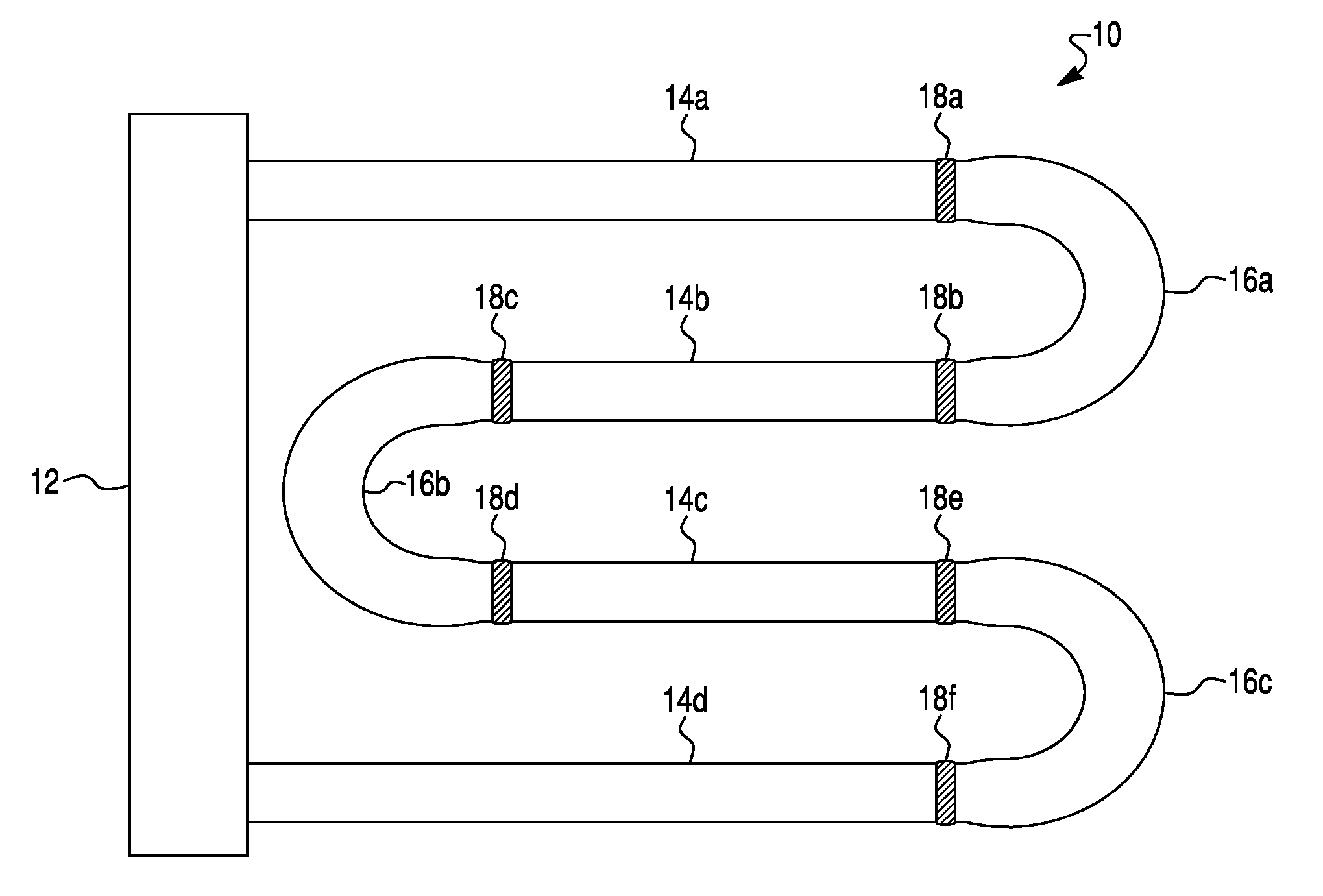
[0029]Reference will now be made in detail to exemplary embodiments and methods of the invention as illustrated in the accompanying drawings, in which like reference characters designate like or corresponding parts throughout the drawings. It should be noted, however, that the invention in its broader aspects is not limited to the specific details, representative devices and methods, and illustrative examples shown and described in connection with the exemplary embodiments and methods.

[0030]For purposes of the following description, certain terminology is used in the following description for convenience only and is not limiting. The words “top”, “bottom”, “right”, “left”, “lower”, “upper”, “inner” and “outer” designate directions in the drawings to which reference is made. The words “uppermost” and “lowermost” refer to position in a vertical direction relative to a geometric center of the apparatus of the present invention and designated parts thereof. The terminology includes the ...


PUM

PropertyMeasurementUnit
Fractionaaaaaaaaaa
Radiusaaaaaaaaaa
Distanceaaaaaaaaaa

Abstract

Nickel-base radiant tube includes straight and curved elbow tube sections. The straight tube section has constant inner and outer radii. The elbow tube section has a constant inner radius and variable outer radius. The inner diameter of the elbow tube section is equal the inner radius of the straight tube section. Mating end portion of the elbow tube section has an outer radius equal to the outer radius of the straight tube section. Method for making the radiant tube comprises the steps of positioning a mating end portion of the straight tube section adjacent to and aligned with the mating end portion of the elbow tube section so that end faces of the straight and elbow tube sections face each other to define a circumferentially extending weld groove, and butt welding the mating end portions of the straight and elbow tube sections together at the weld groove.

Description

CROSS-REFERENCE TO RELATED APPLICATION[0001]This Application claims the benefit under 35 U.S.C. 119(e) of U.S. Provisional Application No. 61 / 358,639 filed Jun. 25, 2010 by Sree Harsha Lalam et al.BACKGROUND OF THE INVENTION[0002]1. Field of the Invention[0003]The present invention relates to methods for making radiant tubes in general and, more particularly, to a method for making a nickel-base radiant tube comprising straight and elbow tube sections having different thicknesses.[0004]2. Description of the Related Art[0005]Radiant tubes used to heat industrial furnaces are well known. Usually, in a radiant tube furnace, products of combustion from a burner are confined within a radiant tube with the material to be heated neighboring or surrounding the radiant tube. The heat from the burner is indirectly transferred to the material via the radiant tube, primarily by radiation and secondarily by convection. In a radiant tube furnace, the material being heated is isolated from the pro...

Claims


Application Information

Patent Timeline
IPC IPC(8): F16L13/02B23K28/00
CPCB23K9/0282B23K33/006B23K2201/06C10G9/20F28F2275/06F28D2021/0056F28F9/26F28F21/087F16L13/02B23K2101/06
Inventor LALAM, SREE HARSHA
Owner ARCELORMITTAL INVESTIGACION Y DESARROLLO SL
Why Eureka
Try Eureka