FSW (Friction-stir Welding) method assisted by heat source

A technology of friction welding and auxiliary stirring, which is applied in welding equipment, non-electric welding equipment, metal processing equipment, etc., and can solve the problems of expensive stirring head, low service life, unfavorable batch and large-scale application, etc.

Inactive Publication Date: 2015-04-29
董春林
View PDF4 Cites 29 Cited by
  • Summary
  • Abstract
  • Description
  • Claims
  • Application Information

AI Technical Summary

Problems solved by technology

Since the preheating laser beam is on the back of the welding area, the temperature on the back of the material to be welded will be higher than the temperature on the front, and friction stir welding is a kind of pressure welding, and the back of the weld seam needs rigid support, so the heat required for friction stir welding still requires a stirring head Friction with the base metal is g

Method used


Image

  • FSW (Friction-stir Welding) method assisted by heat source

Examples


Embodiment 1

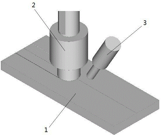
[0031]The thickness of TC4 to be welded is 10mm, and auxiliary heating and friction stirring heads 2 are arranged in sequence along the welding direction; the auxiliary heat source comes from electric arc or plasma, and the included angle between the center line of arc or plasma gun and the vertical direction of the upper surface of TC4 plate (forward Angle) is α=30°, the auxiliary heat source parameters are: maximum current 500A (welding current is 170A), shielding gas: argon, electrode protrusion length: 15 ~ 17mm, electrode distance: 2mm, TIG torch angle: forward Angle 30 °, tungsten electrode (negative): diameter 4mm, electrode rod front end angle 60 °; The center line of the friction stirring head is the same as the included angle of the vertical direction on the TC4 board surface, where θ=2.5 °; The distance between the action point of the auxiliary heat source and the action point of the friction stirring head on the surface of the stainless steel plate is 15mm, the movi...

Embodiment 2

[0033] The material to be welded is copper plate (T1) and aluminum plate (6063) with a thickness of 10mm butt joint, and auxiliary heating (alloyed welding wire as electrode) and friction stirring head 2 are arranged in sequence along the welding direction; the auxiliary heat source comes from MIG, and the center line of the welding torch is the same as The included angle (advance angle) of the vertical direction on the surface of the test plate is α=30°, the parameters of the auxiliary heat source are: the maximum current is 500A (the welding current is 170A), the shielding gas: argon, the protruding length of the alloyed welding wire: 15 ~ 17mm, electrode distance: 2mm, MIG torch angle: advance angle 30°, wire electrode (negative): diameter 3mm, electrode rod front end angle 60°; the center line of the friction stirring head is perpendicular to the surface of the TC4 plate The included angle is θ, wherein θ=2.5°; the distance between the point of action of the auxiliary heat ...


PUM


Abstract

The invention discloses an FSW (Friction-stir Welding) method assisted by a heat source. The method comprises the following steps of: A, splicing and fixing to-be-welded materials, preheating to-be-welded regions by an auxiliary heat source until the welded materials are in a plasticized or alloyed state; and B, enabling the auxiliary heat source and a friction-stir head to be positioned on same pair of butt welding wires, and after the welded materials are heated to be in the plasticized state, enabling the friction-stir head to advance along the heating path of the auxiliary heat source so as to perform friction welding. The invention provides a composite welding method which is reasonable in cost, long in service life of stir head, capable of realizing high high-melting-point metal and dissimilar metal welding speed, and high in welding quality. According to the welding method, the service life problem of the stir head of high-melting-point metal FSW and the problem of dissimilar metal FSW welded seam alloying are successfully solved, the welding cost of the high-melting-point metal and the welding cost of the dissimilar metal are greatly lowered and the welding quality is improved.

Description

technical field [0001] The invention relates to the field of welding technology, in particular to a heat source assisted friction stir welding method. Background technique [0002] Since the friction stir welding is a solid-phase welding method that uses the high-speed rotating stirring head and the shaft shoulder to be in a plastic state with the metal. As the stirring head advances, the metal moves to the rear of the stirring head to form a solid-phase welding method. The high-temperature strength, hardness, and toughness requirements of the stirring head are extremely strict, and currently it is only used in the welding of non-ferrous metals such as Al, Cu and other low-melting point metals. Due to the high melting point of high melting point metals, it is difficult to make the material to be welded reach a plastic state only by the friction between the stirring head and the base metal. During the friction stir welding process of dissimilar metal materials, intermetallic ...

Claims


Application Information

Patent Timeline
IPC IPC(8): B23K20/12B23K20/26B23K28/02
CPCB23K20/122B23K28/02
Inventor 董春林谭锦红邓军
Owner 董春林
Why Eureka
Try Eureka