
A pressure reducing device and method for a supercritical water system

A depressurization device, supercritical water technology, applied in chemical instruments and methods, water pollutants, special compound water treatment, etc. , The effect of avoiding valve failure problems

Active Publication Date: 2018-07-17
XI AN JIAOTONG UNIV +1
View PDF5 Cites 0 Cited by
  • Summary
  • Abstract
  • Description
  • Claims
  • Application Information

AI Technical Summary

Problems solved by technology

[0006] The purpose of the present invention is to overcome the problem of unreliable depressurization in supercritical water treatment systems, and provide a depressurization device and method for supercritical water systems, which can not only effectively avoid abrasion, clogging and unreliable pressure reduction of a single valve. Reliable problem, also enables precise control of system pressure

Method used


Image

  • A pressure reducing device and method for a supercritical water system
  • A pressure reducing device and method for a supercritical water system
  • A pressure reducing device and method for a supercritical water system

Examples


Embodiment 1

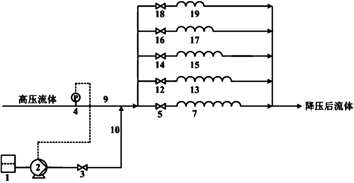
[0032] Such as figure 1 As shown, the decompression system includes a decompression branch, a start-stop branch and a resistance water branch. The decompression branch includes a capillary pressure reducer 7 , the inner diameter of which is in the range of 1-10 mm, and the capillary pressure reducer 7 is connected to the second cut-off valve 5 . The start-stop branch includes a first regulating valve 8 connected to the third cut-off valve 6 . The step-down branch and the start-stop branch are connected in parallel. The resistance water branch includes a resistance water storage tank 1 , the outlet of the storage tank 1 is connected to the inlet of the resistance water pump 2 , the outlet of the resistance water pump 2 is connected to the first stop valve 3 , and the first stop valve 3 is connected to the resistance water connection pipe 10 . After the supercritical water oxidation reaction, the high-pressure fluid flows into the post-reaction liquid pipe 9, and the outlet of...

Embodiment 2

[0036] Such as figure 2 As shown, the first regulating valve 8 in Embodiment 1 is replaced by a back pressure regulating valve 11 . System pressure control during system startup and shutdown is realized by adjusting the back pressure valve.

[0037] The step-down process is as follows:

[0038]During the start-up stage of the system, the resistance water pump 2 is not started, the second cut-off valve 5 of the step-down branch is closed, and the third cut-off valve 6 of the start-stop branch is opened. As the system is filled with water, gradually adjust the back pressure valve 11 to gradually increase the system pressure to the set operating pressure. Open the second cut-off valve 5 of the step-down branch, close the third cut-off valve 6, and at the same time turn on the resistance water pump 2, so that the resistance water flows through the capillary 7, and gradually increase the flow of the water pump until the system pressure rises to the set working pressure. During ...

Embodiment 3

[0040] Such as image 3 As shown, the first regulating valve 8 in Embodiment 1 is replaced by a group of first capillary tube 13 , second capillary tube 15 , third capillary tube 17 and fourth capillary tube 19 connected in parallel with increasing lengths in sequence. System pressure control during system startup and shutdown is achieved by switching different capillary branches.

[0041] The step-down process is as follows:

[0042] During the start-up phase of the system, the resistance water pump 2 is not started, and the second cut-off valve 5 , the fourth cut-off valve 12 , the fifth cut-off valve 14 and the sixth cut-off valve 16 are closed. Open the seventh shut-off valve 18, and gradually increase the reactor pressure to the set operating pressure I as the system is filled with water. Open the sixth shut-off valve 16 and close the seventh shut-off valve 18 until the reactor pressure gradually rises to the set operating pressure II. Open the fifth shut-off valve 14 ...


PUM


Abstract

The invention discloses a pressure reduction device and method of a supercritical water system. The pressure reduction device comprises a pressure reduction branch, startup-shutdown branches and a resistance water branch, wherein a high-pressure fluid flows into an inlet of the pressure reduction branch and flows out of an outlet of the pressure reduction branch after pressure reduction and the startup-shutdown branches are parallelly connected to the two ends of the pressure reduction branch. The pressure reduction of the system is achieved through on-way resistance when a material flows through capillary tubes, and valve failure easily caused during one-step pressure reduction achieved by adopting a single valve is effectively avoided. In addition, the problems of abrasion and blockage of internal elements of the valve in the pressure reduction process of the material containing solid particles can be further prevented, and the accurate system pressure control can be achieved by adjusting the flow of the resistance water to be led to the capillary tubes. Furthermore, step-by-step pressure rise or reduction in the startup or shutdown process of the system is achieved by being matched with a regulating valve or a counterbalance valve which are connected in parallel.

Description

【Technical field】 [0001] The invention belongs to the fields of environmental protection and chemical industry, and in particular relates to a pressure reducing device and method for a supercritical water system. 【Background technique】 [0002] Supercritical Water Oxidation (SCWO for short), as a new organic waste treatment technology, uses the special properties of water in the supercritical state (Tc=374°C, Pc=22.1MPa) to make organic matter It is completely soluble in supercritical water with oxidants, and a homogeneous oxidation reaction occurs rapidly, quickly and thoroughly transforming organic matter into harmless CO2, N2, H2O and other small molecule compounds. This is because near or above the critical point of pure water, the thermophysical properties of water change significantly compared to water at normal temperature. The significant reduction of the dielectric constant leads to a significant increase in the solubility of hydrocarbons and gases such as O2, N2 a...

Claims


Application Information

Patent Timeline
Patent Type & Authority Patents(China)
IPC IPC(8): C02F1/72
CPCC02F1/72C02F2101/30C02F2305/02
Inventor 王树众张洁王来升任萌萌李艳辉孙盼盼
Owner XI AN JIAOTONG UNIV
Learn More