
Hydrocarbon material hydrogenation method and combined expanded bed hydrogenation reactor

A hydrogenation reactor and hydrogenation reaction technology, which are applied in the fields of hydrotreating process, chemical instruments and methods, and petroleum industry, etc., can solve the problems of inability to achieve clear separation, difficulty in ensuring long-term stable work, and reduced separation efficiency.

Inactive Publication Date: 2016-05-25
何巨堂
View PDF12 Cites 30 Cited by
  • Summary
  • Abstract
  • Description
  • Claims
  • Application Information

AI Technical Summary

Problems solved by technology

[0026] ① Since the flash gas R1PXV containing solid particles from R1P belongs to the saturated vapor phase, it must entrain liquid droplets. When the gas S10V contains high-viscosity hydrocarbon components, the cyclone separator will be affected by the solid and heavy hydrocarbons formed in the flow channel. Combined deposition reduces separation efficiency, and it is difficult to guarantee long-term stable work;
[0027] ②Because the gas R1PXV belongs to the saturated vapor phase, it must entrain liquid mist droplets. When the gas S10V contains solid particles with a small particle size, the upper limit of the separation efficiency of the cyclone separator is limited due to the adhesion of the mist droplets to the particles. Realize clear separation, that is, the high-fraction gas S10V is not worthy of the name as a purified gas. If a single-stage high-pressure operating system is adopted, it will lead to a high content of solid particles in the R20 raw material in the second hydrogenation upgrading reaction process. The consequences are: or lead to the use of fixed beds The reactor catalyst bed plugging shortens the operation cycle, or is forced to adopt an upflow reactor such as an ebullating bed reactor, which increases investment and operating costs
[0050] Method of the present invention has no report

Method used


Image

  • Hydrocarbon material hydrogenation method and combined expanded bed hydrogenation reactor
  • Hydrocarbon material hydrogenation method and combined expanded bed hydrogenation reactor
  • Hydrocarbon material hydrogenation method and combined expanded bed hydrogenation reactor

Examples


Embodiment 1

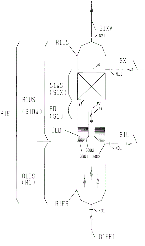
[1263] The first hydrogenation reaction process R1 is a hydrogenation process using a suspended bed for the heavy fraction of medium and low temperature coal tar whose conventional boiling point is higher than 350°C; two suspended bed hydrogenation reactors are used in series; the first suspended bed The hydrogenation reactor is a conventional suspended bed hydrogenation reactor, that is, it does not have the function of product separation and gas phase washing; the second suspension bed hydrogenation reactor is figure 1 The combined suspended bed reactor with the structure shown is equipped with a hot and high-pressure separation gas washing process S1DW, and a flashing step S1 and a washing step S1X.

[1264] The hydrocarbon condensed liquid obtained by cooling the hot high fraction gas S1V is used as washing oil SX by gravity flow.

[1265] The heat exchanger HX100 for cooling the hot high fraction gas S1V to obtain the washing oil SX is arranged on the upper platform of th...

Embodiment 2

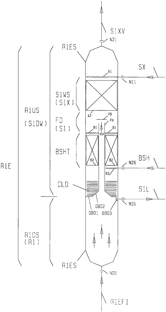
[1267] The first hydrogenation reaction process R1 is a hydrogenation process using a suspended bed for the heavy fraction of medium and low temperature coal tar whose conventional boiling point is higher than 350°C; two suspended bed hydrogenation reactors are used in series; the first suspended bed The hydrogenation reactor is a conventional suspended bed hydrogenation reactor, that is, it does not have the function of product separation and gas phase washing; the second suspension bed hydrogenation reactor is figure 2 The combined suspended bed reactor with the structure shown is equipped with a hot and high-pressure separation gas washing process S1DW, and a flashing step S1 and a washing step S1X.

[1268] The hydrocarbon condensed liquid obtained by cooling the hot high fraction gas S1V is used as washing oil SX by gravity flow.

[1269] The heat exchanger HX100 for cooling the hot high fraction gas S1V to obtain the washing oil SX is arranged on the upper platform of t...

Embodiment 3

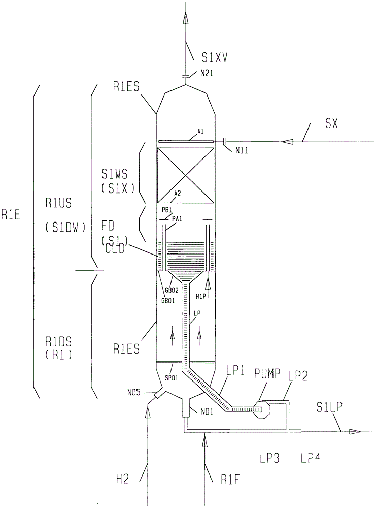
[1271] The first hydrogenation reaction process R1 is a hydrogenation process using an ebullating bed for the heavy fraction of medium and low temperature coal tar whose conventional boiling point is higher than 350°C; two ebullating bed hydrogenation reactors are used in series; the first ebullating bed The hydrogenation reactor is a conventional ebullated bed hydrogenation reactor, that is, it does not have the function of product separation and gas phase washing; the second ebullating bed hydrogenation reactor is image 3 The combined ebullating bed reactor with the structure shown is equipped with a hot and high-pressure separation gas washing process S1DW, a flashing step S1, and a washing step S1X.

[1272] The hydrocarbon condensed liquid obtained by cooling the hot high fraction gas S1V is used as washing oil SX by gravity flow.

[1273] The heat exchanger HX100 for cooling the hot high fraction gas S1V to obtain the washing oil SX is arranged on the upper platform of ...


PUM


Abstract

The invention relates to a hydrocarbon material hydrogenation method and a combined expanded bed hydrogenation reactor. The method is suitable for a medium / low-temperature coal tar heavy-fraction hydrogenation thermal cracking process and an oil preparation process from coal by direct hydrogenation, can implement integration of the reaction section and the reaction product R1P comprehensive separation section, and can implement cooling on the R1P immediately to inhibit the heavy component thermal condensation reaction and / or implement washing to lower the solid content or dissolve and rectify the solids in the gas product so as to lower the heavy hydrocarbon content in the gas product. The reactor R1E is provided with a lower section R1DS (expanded bed reaction region) and an upper section R1US (thermal high-pressure separation gas washing region), the R1P enters the R1US and is separated in the flash distillation space into a gas R1PV possibly containing solids and a liquid stream S1L possibly containing solids, the gas R1PV contacts washing oil SX and is washed and separated into rich washing oil SXK and gas S1V, and at least part of the stream S1L or distillate oil thereof returns to the lower section R1DS to perform cyclic reaction.

Description

technical field [0001] A hydrocarbon material hydrogenation method and its combined expanded bed hydrogenation reactor, suitable for the hydrothermal cracking process of medium and low temperature coal tar heavy fractions, and the direct coal hydrogenation process for oil production, which can realize the synthesis of the reaction section and the reaction product R1P The integration of the separation section can reduce the temperature of R1P at the first time to suppress the thermal condensation reaction of heavy components and or wash to reduce the solid content in the gas product and or dissolve and rectify to reduce the heavy hydrocarbon content in the gas product. Reactor R1E The lower R1DS is the expanded bed reaction zone and the upper R1US is the thermal high-pressure separation gas washing zone. R1P enters the R1US and is separated into the gas R1PV that may contain solids and the liquid stream S1L that may contain solids in the flash space. The gas R1PV is in contact w...

Claims


Application Information

Patent Timeline
IPC IPC(8): C10G65/02B01J8/02
CPCC10G65/02B01J8/02
Inventor 何巨堂
Owner 何巨堂
Learn More