
Large-size and high specific stiffness truss off-axis three-reflection optical system main support structure

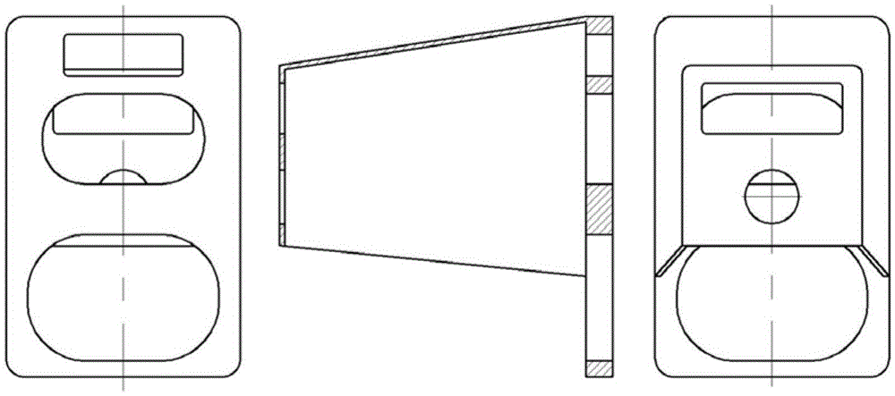
An off-axis three-mirror and optical system technology, applied in the field of space optical remote sensing, can solve the problems of difficult and large-scale thin-walled cylinder structure integral casting, low yield, warping deformation, etc., achieving good dimensional stability and saving launch costs. , easy to assemble effect

Active Publication Date: 2016-05-25
CHANGCHUN INST OF OPTICS FINE MECHANICS & PHYSICS CHINESE ACAD OF SCI
View PDF5 Cites 14 Cited by
  • Summary
  • Abstract
  • Description
  • Claims
  • Application Information

AI Technical Summary

Problems solved by technology

[0003] 1) Lower specific stiffness
Materials such as cast titanium alloy have high density and low elastic modulus, resulting in low specific stiffness of thin-walled cylindrical structural parts, and it is difficult to meet the design requirements at the same time for weight and stiffness
[0004] 2) It is difficult to form
The supporting structure of the thin-walled cylinder is integrally cast, which is generally formed by mold casting. The structure of the off-axis three-reverse space remote sensor is complex. If the thin-walled cylinder structure is used, the design and processing of the mold are relatively difficult, and the thin-walled structural parts are prone to appear. Poor forming, warping deformation, cold shut, cracks and other casting defects, low yield
And limited by the current domestic casting capacity, it is difficult to realize the overall casting of large-sized thin-walled cylindrical structures, so the thin-walled cylindrical support structure cannot meet the requirements of large-sized optical systems

Method used


Image

  • Large-size and high specific stiffness truss off-axis three-reflection optical system main support structure
  • Large-size and high specific stiffness truss off-axis three-reflection optical system main support structure
  • Large-size and high specific stiffness truss off-axis three-reflection optical system main support structure

Examples


Embodiment Construction

[0033] The present invention will be described in detail below in conjunction with the accompanying drawings.

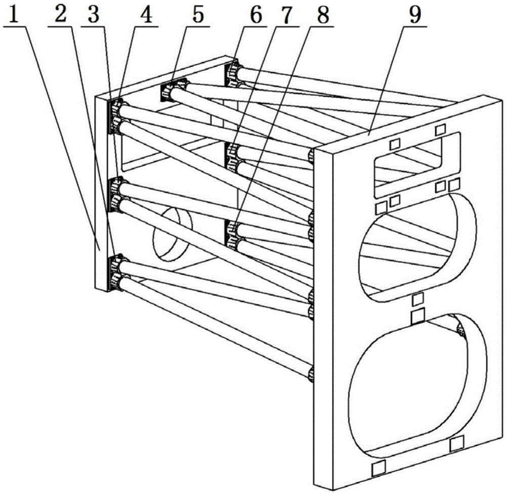
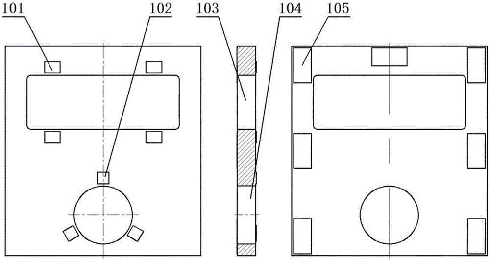
[0034] The best embodiment of the present invention is as Figure 2 to Figure 9 As shown, it mainly includes the front plate 1, the first A-shaped truss 2, the second A-shaped truss 3, the third A-shaped truss 4, the fourth A-shaped truss 5, the fifth A-shaped truss 6, and the sixth A-shaped truss 7 , the seventh A-shaped truss 8 , the rear plate 9 . Seven sets of A-type trusses are combined with the front plate 1 and the rear plate 3 through screw connections, among which the first A-type truss 2 and the seventh A-type truss 8 are symmetrically distributed on the left and right sides of the main support structure, and the second A-type truss Truss 3 and the sixth A-shaped truss 7 are symmetrically distributed on the left and right sides of the main support structure, the third A-shaped truss 4 and the fifth A-shaped truss 6 are symmetrically distributed on the left...


PUM


Abstract

The present invention relates to a large-size and high specific stiffness truss off-axis three-reflection optical system main support structure which mainly comprises a, front plate, a first A-type truss, a second A-type truss, a third A-type truss, a fourth A-type truss, a fifth, A-type truss, a sixth A-type truss, a seventh A-type truss, and a back plate. The technical point is that the seven groups of A-type trusses are combined to the front plate and the back plate through the mode of a threaded connection. Each of the A-type truss comprises an A-type joint, a truss rod, and an I-type joint. The truss rod and the joint are combined together through the mode of glue connection, the mode of glue connection is a sleeve mode, the joint is outside, and the truss rod is inside. The A-type joint is fixed on the front plate, and the I-type joint is fixed at the back plate. The large-size and high specific stiffness truss off-axis three-reflection optical system main support structure has the advantages of compact structure, easy formation of each structure member, easy assembly of a main support structure and a high specific stiffness and can satisfy the use requirement of a large size off-axis three-reflection optical system. The main support structure can be used in the field of large space sensors, space-based telescopes and the like.

Description

technical field [0001] The invention belongs to the field of space optical remote sensing and relates to a main support structure of a truss type off-axis three-mirror optical system with large size and high specific stiffness. Background technique [0002] The off-axis three-mirror optical system has been widely used in the field of space optical remote sensing due to its advantages of no central obstruction, high transfer function, compact structure, and easy realization of large field of view and high resolution at the same time. At present, the main support structure of the off-axis three-mirror optical system usually adopts an integrally cast thin-walled tube structure, such as figure 1 As shown, the materials are generally cast titanium alloy, invar, boron aluminum alloy and other materials. When the size of the remote sensor is large, the integrally cast thin-walled cylinder structure cannot meet the requirements of use. This structure has the following disadvantage...

Claims


Application Information

Patent Timeline
IPC IPC(8): G02B7/182
CPCG02B7/182
Inventor 李志来张学军杨利伟辛宏伟杨会生
Owner CHANGCHUN INST OF OPTICS FINE MECHANICS & PHYSICS CHINESE ACAD OF SCI
Learn More