
Micro-torsion mirror driven by one-side unequal height comb teeth

A technology of micro-torsional mirrors and comb teeth is applied in the field of high-comb electrostatically driven micro-torsional mirrors and their preparation. Effect

Active Publication Date: 2016-05-25
XIAN LEADMEMS MICROSYST TECH CO LTD
View PDF20 Cites 10 Cited by
  • Summary
  • Abstract
  • Description
  • Claims
  • Application Information

AI Technical Summary

Problems solved by technology

[0004] However, since the micro-torsion mirror driven by the vertical non-offset comb made of SOI has a random vibration direction; The feedback signal obtained by the change of capacitance between the capacitors cannot reflect the starting direction of the vibration.

Method used


Image

  • Micro-torsion mirror driven by one-side unequal height comb teeth
  • Micro-torsion mirror driven by one-side unequal height comb teeth
  • Micro-torsion mirror driven by one-side unequal height comb teeth

Examples


Embodiment 1

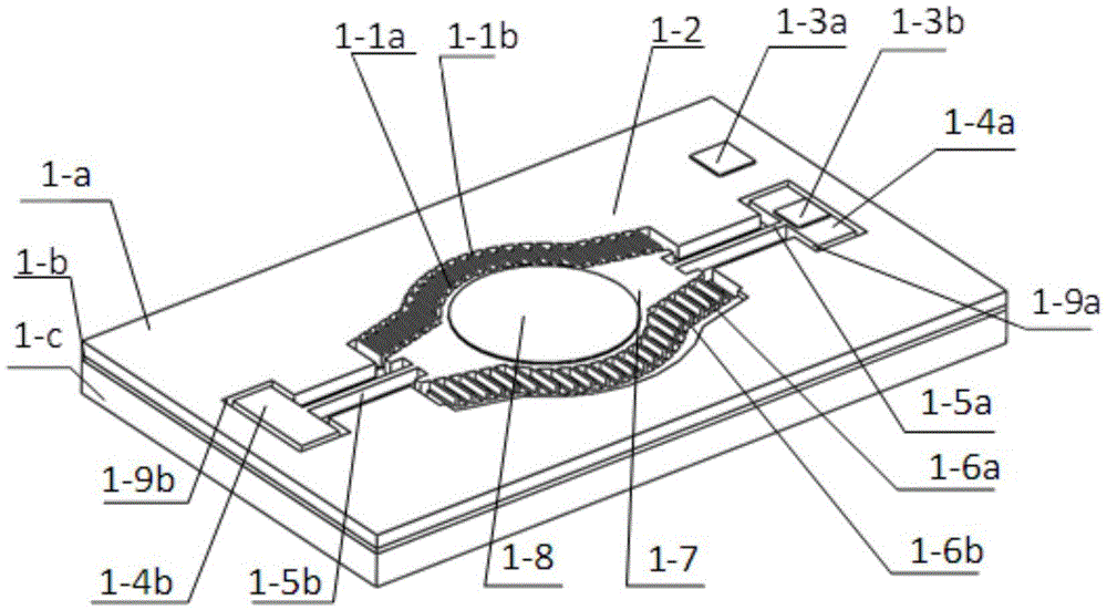
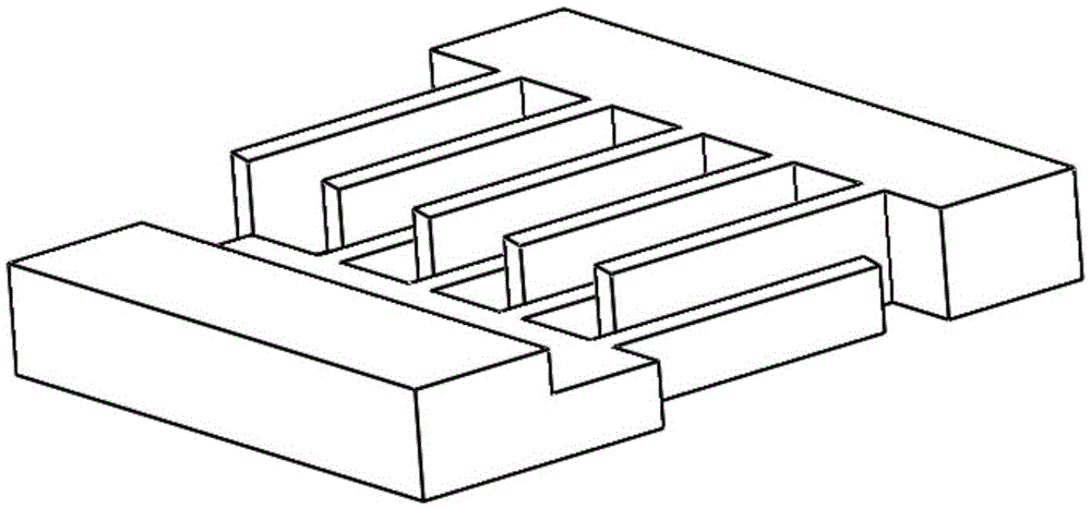
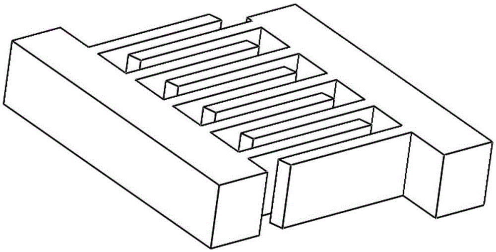
[0023] The present invention proposes a micro-torsion mirror driven by comb teeth with unequal heights on one side. The micro-torsion mirror is made of SOI silicon wafer, and mainly consists of a device layer 1-a, a buried oxide layer 1-b, and a base layer 1-c. Composed of three layers, its structure is as follows figure 1 shown. The base layer 1-c is used to make the back cavity structure to provide movable space for the movable mirror; the buried oxide layer 1-b is used for the electrical isolation of the device layer 1-a and the base layer 1-c; the device layer 1-a is used for The structure of each part of the micro-torsion mirror, including the movable mirror structure 1-7 and the reflective layer 1-8 on it, the first torsion support beam 1-5a, 1-5b and its anchor point 1-4a, 1 -4b, the first comb structure 1-1 and the second comb structure 1-6, comb anchor points and pads 1-3a, 1-3b, etc.; wherein, the first comb structure 1-1 and the second Comb tooth structures 1-6 ar...

Embodiment 2

[0033] refer to Figure 4 , a two-dimensional micro-torsion mirror driven by combs with unequal heights on one side based on SOI, which is proposed in this embodiment, consists of three layers: a device layer 1-a, a buried oxide layer 1-b in the middle, and a base layer 1-c composition. The base layer 1-c is used to make a back cavity structure, which provides movable space for the movable mirror structure 1-7 and the movable frame 6-4; the buried oxide layer 1-b is used for the electrical connection between the device layer 1-a and the base layer 1-c. isolation. The device layer 1-a is used to make the movable mirror structure 1-7 and the reflective layer 1-8 thereon, the first torsion support beams 1-5a and 1-5b of the movable mirror structure 1-7, and the movable mirror structure The first comb tooth structure, the movable frame 6-4 supporting the first torsion support beam of the movable mirror structure, the second torsion support beams 6-8a and 6-8b of the movable fram...


PUM


Abstract

The invention discloses a micro-torsion mirror driven by one-side unequal height comb teeth, a device layer of the mirror is used for manufacturing a movable mirror surface structure of the micro-torsion mirror and a reflecting layer and a torsional supporting beam of the movable mirror surface structure and structures including a fixed anchor point, a dynamic and static comb teeth pair, a static comb anchor point, a pad and the like; a substrate layer is used for manufacturing a back cavity; and a buried oxide layer is used for electrical isolation between the device layer and the substrate layer. For solving the problem that the oscillation starting direction of the micro-torsion mirror driven by equal height comb teeth manufactured by SOI is uncontrollable and can not identified through capacitance detection, the thickness of the comb teeth is changed, the dynamic comb teeth and static comb teeth on one side of the torsional supporting beam are manufactured as an unequal height comb teeth pair, the other side maintains an equal height comb pair, the capacitance maximum value position of the comb teeth pairs on the two sides of the torsional supporting beam is deviated a structure balance position of the movable mirror surface structure, the oscillation starting direction the manufactured micro-torsion mirror is ensured, the direction information is provided through the capacitance detection, so that the closed-loop control is realized.

Description

【Technical field】 [0001] The invention belongs to the field of Micro-Opto-Electro-Mechanics (MOEMS), relates to Micro-Electro-Mechanical Systems (MEMS) technology and micro-machining technology, in particular to a single-side unequal-height comb-teeth electrostatically driven micro-torsion mirror based on SOI technology and a preparation method thereof. 【Background technique】 [0002] Compared with traditional beam deflection elements, micro-torsion mirrors have the advantages of low energy consumption, miniaturization, and easy integration. Their applications in consumer electronics, communications, biomedicine, military defense, and other fields continue to expand, and they are research hotspots in the field of optical MEMS. Electrostatic comb-driven micro-torsional mirrors, especially the vertical non-offset comb-driven micro-torsional mirrors based on monolithic silicon-on-insulator (SOI), have a simple structure, high energy density, can achieve large rotation angles, an...

Claims


Application Information

Patent Timeline
IPC IPC(8): G02B26/08B81B5/00
CPCB81B5/00G02B26/0833
Inventor 孙明宋秀敏
Owner XIAN LEADMEMS MICROSYST TECH CO LTD
Learn More