Layered equalizing circuit system based on series battery stack and hybrid control method
A technology of series battery packs and balancing circuits, applied in charge balancing circuits, battery circuit devices, secondary battery charging/discharging, etc., can solve problems such as battery imbalance, high current stress, increased circuit loss and cost, etc.
- Summary
- Abstract
- Description
- Claims
- Application Information
AI Technical Summary
Problems solved by technology
Method used
Image
Examples
Embodiment 1
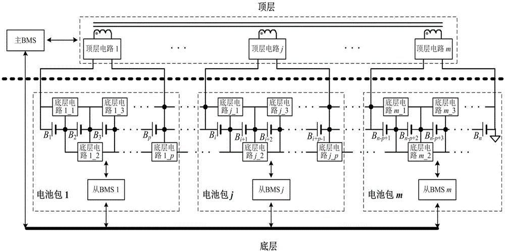
[0068] figure 2 A hierarchical equalization architecture diagram based on series battery packs is given. The system is divided into top-level and bottom-level equalization structures. The bottom layer adopts a C2C equalization architecture. Every two adjacent battery cells are equalized by an equalization circuit. The input and output ends of the circuit are respectively connected to two adjacent battery cells. The circuit topology can choose bidirectional converters such as bidirectional BuckBoost, bidirectional Cuk, and switched capacitors. The n battery cells are divided into m battery packs, and each battery pack contains p battery cells (p=n / m, if there is a remainder, round up to an integer). On this basis, each battery pack is connected to one winding of a multi-winding transformer through a power conversion circuit (such as half-bridge, full-bridge, push-pull, etc.), so as to couple with other battery packs and perform energy transfer, forming a multi-directional mult...
Embodiment 2
[0072] Figure 4 The topological structure of the top-level equalization circuit of the present invention is given. The circuit is based on the phase-shifted half-bridge topology, the first switching tube Q i_1 and the second switch Q i_2 (i=1, 2, . . . , m) are connected in series to form a bridge arm, and the two switching tubes are turned on complementary with a 50% duty cycle. The first resonant capacitor C i_1 with the second resonant capacitor C i_2 Connected in series to form another bridge arm. Inductance L r_i It is the leakage inductance of the transformer, which is connected in series with one winding of the transformer at the midpoint of the two bridge arms. Each winding of the transformer is coupled to other windings through a magnetic core. When energy needs to be transferred between any two battery packs, taking the 1st and mth as an example, the main BMS sends a PWM signal to make Q 1_1 and Q m_1 They are conducted at a certain phase shift angle, and t...
Embodiment 3
[0075] Figure 7 , Figure 8 The block diagram and control flow chart of the hybrid control mode of the present invention are given respectively.
[0076] The voltage, charge and discharge current, and temperature information of each battery cell are obtained by sampling from the BMS, and the battery capacity, SOC, SOC change rate, and current acceptance rate are estimated. When the battery is in a static state, the main BMS uses the SOC as the control object; when the battery is in the working state, uses the SOC change rate as the control object to calculate the operating current reference corresponding to each equalization circuit.
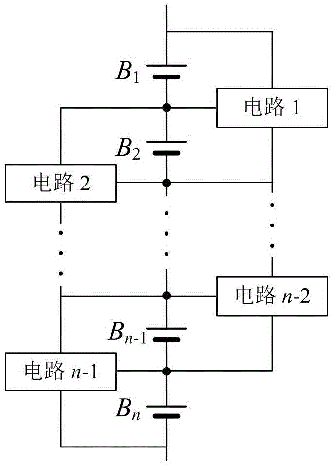
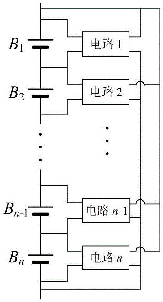
[0077]It can be seen from Figure 1(a) that in the underlying C2C architecture equalization system, the equalization current I flowing through the i-th battery cell b_i It is equal to the working current I of two adjacent balancing circuits of the battery c_i , I c_i-1 And the difference between the working current of the top-level equalizat...
PUM
 Abstract
Description
Claims
Application Information
 - R&D
- Intellectual Property
- Life Sciences
- Materials
- Tech Scout
- Unparalleled Data Quality
- Higher Quality Content
- 60% Fewer Hallucinations
Browse by: Latest US Patents, China's latest patents, Technical Efficacy Thesaurus, Application Domain, Technology Topic, Popular Technical Reports.
© 2025 PatSnap. All rights reserved.Legal|Privacy policy|Modern Slavery Act Transparency Statement|Sitemap|About US| Contact US: help@patsnap.com


