Liquid-cooling drum brake with cooling liquid circulation control system

A circulation control and coolant technology, applied in the direction of brake types, brake parts, mechanical equipment, etc., can solve the problems of difficulty in fully exerting functions, poor thermal stability, low heat dissipation capacity, etc., and achieve thermal stability and good heat dissipation , good thermal stability and heat dissipation, and the effect of improving thermal stability

Active Publication Date: 2016-06-01
江苏骏马压路机械有限公司
View PDF6 Cites 5 Cited by
  • Summary
  • Abstract
  • Description
  • Claims
  • Application Information

AI Technical Summary

Problems solved by technology

[0004] The disadvantages of air-cooled drum brakes are poor thermal stability and low heat dissipation. When the car brakes continuously down long slopes and frequently brakes on urban roads, the friction plate and the air-cooled brake drum will rub for a long time, resulting in air-cooled brakes. The temperature of the brake is too high. Since the material of the friction plate contains organic polymers such as resin, as the temperature of the friction plate and the air-cooled brake drum increases, the friction coefficient between the friction plate and the air-cooled brake drum decreases, so that The braking efficiency of the air-cooled drum brake is reduced, the brake is "soft", and thermal decay occurs, the thermal stability is poor, and when the thermal degradation is severe, the role of the braking force adjustment system such as the automobile anti-lock braking device is difficult to be fully utilized. As a result, too many traffic accidents have occurred, which is a major safety problem that has not been solved so far in the automotive braking system.

Method used


Image

  • Liquid-cooling drum brake with cooling liquid circulation control system
  • Liquid-cooling drum brake with cooling liquid circulation control system
  • Liquid-cooling drum brake with cooling liquid circulation control system

Examples


Embodiment Construction

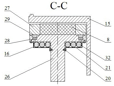
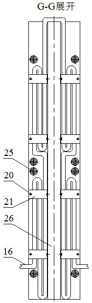
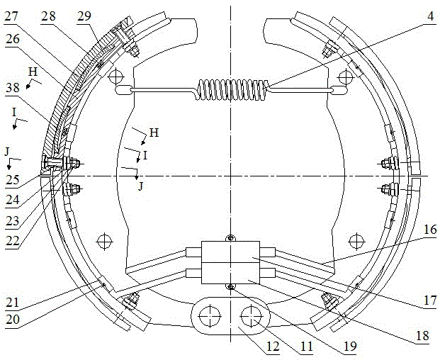
[0038] Liquid-cooled drum brakes with coolant circulation control systems include liquid-cooled drum brakes and coolant circulation control systems such as Figure 4 ?18.

[0039] In a liquid-cooled drum brake with a coolant circulation control system, the liquid-cooled drum brake includes a cylinder 1, a piston 3, a return spring 4, a bottom plate connecting bolt 5, a friction plate 8, a positioning pin 10, a support pin 11, Support pin gasket 12, support pin nut 13, liquid-cooled brake base plate 14, liquid-cooled brake drum 15, cooling pipe 16, liquid inlet tee 17, liquid outlet tee 18, tee bolt 19, baffle bolt 20 , baffle plate 21, heat transfer plate nut 22, heat transfer plate gasket 23, heat transfer plate spring 24, heat transfer plate bolt 25, liquid-cooled brake shoe 26, heat transfer plate 27, heating resistor 28 and thermal plate 29 ; On the basis of the air-cooled drum brake, replace the air-cooled brake base plate 6, the air-cooled brake drum 9 and the air-coole...


PUM


Abstract

The invention discloses a liquid-cooling drum brake with a cooling liquid circulation control system. The liquid-cooling drum brake comprises a liquid-cooling drum brake body and the cooling liquid circulation control system. On the basis of an air-cooling drum brake, a heat transfer system is mainly additionally arranged, and the liquid-cooling drum brake body is formed. Heat transfer pieces (27) are arranged on the two edges of a friction plate (8) and are connected with a liquid-cooling brake shoe (26) through heat transfer piece bolts (25). Thermosensitive pieces (29) are arranged in an arc long groove of the liquid-cooling brake shoe (26). Heating resistors (28) are arranged in holes of the liquid-cooling brake shoe (26). Cooling pipes (16) are connected with the liquid-cooling brake shoe (26). The two ends of each cooling pipe (16) are connected with a liquid inlet tee joint (17) and a liquid outlet tee joint (18), and the liquid inlet tee joint (17) and the liquid outlet tee joint (18) are connected with the cooling liquid circulation control system. The liquid-cooling drum brake with the cooling liquid circulation control system is used for replacing the air-cooling drum brake on an automobile, and the heat stability and the heat dissipation performance of the drum brake are improved.

Description

technical field [0001] The invention relates to a drum brake, in particular to a liquid-cooled drum brake with a coolant circulation control system. Background technique [0002] The drum brakes on traditional cars are air-cooled drum brakes, such as Figure 1~3 As shown, the bottom plate connecting bolts fix the air-cooled brake bottom plate, and the air-cooled brake bottom plate does not rotate; the air-cooled brake drum rotates with the wheel; one end of the air-cooled brake shoe passes through the support pin, the support pin washer and the support pin nut Hinged with the air-cooled brake base plate; the other end of the air-cooled brake shoe is supported on the piston; the piston is in the cylinder body, the cylinder body is fixed on the air-cooled brake base plate, and there is brake fluid between the two pistons; Return The spring tensions the two air-cooled brake shoes; the positioning pin axially positions the air-cooled brake shoe on the air-cooled brake bottom pla...

Claims


Application Information

Patent Timeline
Patent Type & Authority Applications(China)
IPC IPC(8): F16D65/827
CPCF16D65/827
Inventor 许兆棠马非凡吴笑宇侯波张恒崔晓迪苏航
Owner 江苏骏马压路机械有限公司
Why Eureka
Try Eureka