Petroleum coke particle combustion device

A combustion device, petroleum coke technology, applied in combustion equipment, solid fuel combustion, lighting and heating equipment, etc., can solve the problems of incomplete combustion of coal, increased emission of flue gas pollutants, increased combustion chamber volume, etc., to achieve investment Less, the principle is easy to understand the effect

Inactive Publication Date: 2016-06-01
CENT SOUTH UNIV
View PDF5 Cites 1 Cited by
  • Summary
  • Abstract
  • Description
  • Claims
  • Application Information

AI Technical Summary

Problems solved by technology

[0005] In order to overcome the problems that the position of the combustion surface of the fixed grate type coal combustion device decreases, resulting in an increase in the volume of the combustion chamber, a decrease in the volumetric heat intensity, heat loss from incomplete combustion of coal, and an increase in the emission of flue gas pollutants, the present invention designs a "communicator". Petroleum oil with technical advantages such as "automatically adjusting and fixing the position of the top surface of the coke particle layer" structure, "invariable heat intensity of the combustion chamber volume", "good controllability of the combustion process, low-carbon energy saving and environmental protection, and emission of flue gas pollutants up to the standard" and other technical advantages Coke combustion device

Method used


Image

  • Petroleum coke particle combustion device
  • Petroleum coke particle combustion device
  • Petroleum coke particle combustion device

Examples


Embodiment Construction

[0014] The invention will be further described below in conjunction with the accompanying drawings.

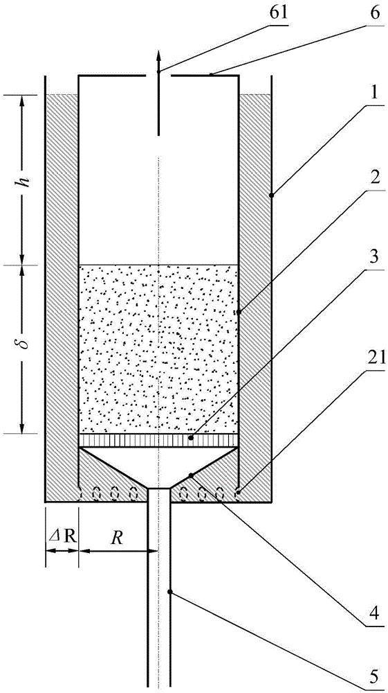
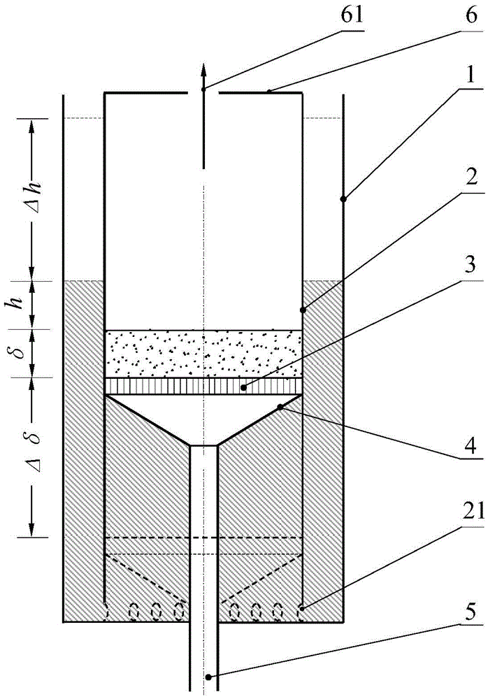
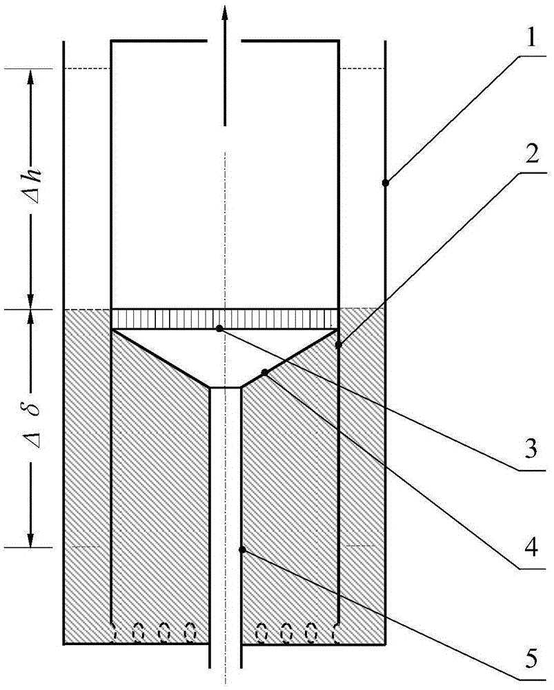
[0015] as attached figure 1 , attached figure 2 And attached image 3 As shown, the petroleum coke particle combustion device mainly includes a furnace shell 1, a furnace liner 2, a furnace bar 3, a pressure equalization chamber 4, an air inlet pipe 5 and a top cover 6. The top cover 6 is in the shape of a disc, and the center of the top cover 6 is provided with a round hole as the smoke outlet 61 . The intake pipe 5 is in the shape of a circular tube and arranged vertically. The pressure equalization chamber 4 is in the shape of an inverted circular platform, surrounded by a large circular bottom, a cylindrical side wall of the circular platform and a small circular bottom. The grate 3 is in the shape of a short cylinder and includes a horizontal top surface, a vertical side wall and a horizontal bottom surface. The furnace liner 2 is in the shape of a long cylinder an...


PUM


Abstract

A petroleum coke particle combustion device mainly comprises an upright cylindric furnace shell, a cylindric furnace inner container, a furnace grate and an air inlet pipe, wherein the central axis of the upright cylindric furnace shell, the central axis of the cylindric furnace inner container, the central axis of the furnace grate and the central axis of the air inlet pipe are collinear. The bottom edge of the furnace inner container is connected with a bottom plate of the furnace shell in a welded manner. The width of a ring cylinder area between the furnace inner container and the furnace shell is 0.41-0.43 time the radius of the furnace inner container. The side wall of the furnace grate is attached to the furnace inner container to vertically move in a seamless manner. Coke particles are stacked above the furnace grate. A combustion chamber is arranged above the coke particle layer. The ring cylinder area between the furnace inner container and the furnace shell and a cylinder area of the furnace inner container are communicated through a plurality of communicating openings in the bottom of the furnace inner container. After the communicating area is filled with pure water, an outer ring cylinder area-inner cylinder area type communicating device is formed, and the height of an outer ring cylinder water column higher than the top face of the coke particle layer is equal to the thickness of the inner cylinder coke particle layer. The petroleum coke particle combustion device can be used for a low-sulfur petroleum coke particle furnace kiln for combustion. According to the petroleum coke particle combustion device, the energy saving rate is larger than 5%-15%, and smoke pollutant discharge meets the requirement of the Integrated Emission Standard of Air Pollutants (GB16297-1996).

Description

technical field [0001] The invention relates to a petroleum coke particle burning device based on the principle of a connecting device, the position of the combustion surface is fixed, and the heat intensity of the volume of the combustion chamber is constant, which is especially suitable for small and medium-sized coal-fired industrial furnaces (including boilers) ) The device is used in the upgrading and transformation of low-carbon energy-saving and emission-reduction technologies. Background technique [0002] The low calorific value of petroleum coke is as high as 33440kJ / kg-37620kJ / kg, and the purchase cost is low. As a fuel to replace coal, it has attracted more and more attention. Taking the price level in 2015 as an example, the market price of petroleum coke is less than half of the market price of heavy oil, and one ton of heavy oil is equivalent to the heat generated by 1.2 tons of petroleum coke. Small and medium-sized coal-fired furnaces (including boilers) wi...

Claims


Application Information

Patent Timeline
Patent Type & Authority Applications(China)
IPC IPC(8): F23B30/02
CPCF23B30/02
Inventor 艾元方艾治文杨天子赵黔涛
Owner CENT SOUTH UNIV
Why Eureka
Try Eureka