Energy-saving environment-friendly circulating fluidized bed system

A circulating fluidized bed, energy saving and environmental protection technology, applied in the field of circulating fluidized bed systems, can solve the problems of poor material return, undisclosed high temperature flue gas, complex structure, etc., to eliminate sparks, ensure safety, and uniform fluidization reaction Effect

Inactive Publication Date: 2016-06-01
GUANGDONG INST OF SPECIAL EQUIP INSPECTION
View PDF9 Cites 3 Cited by
  • Summary
  • Abstract
  • Description
  • Claims
  • Application Information

AI Technical Summary

Problems solved by technology

However, the circulating fluidized bed system designed in this patent needs to use multi-stage refeeders in series to solve the problem of poor refeeding in the circulating fluidized bed system, the structure is too complicated, and it does not disclose how to recycle the discharged high-temperature flue gas

Method used


Image

  • Energy-saving environment-friendly circulating fluidized bed system
  • Energy-saving environment-friendly circulating fluidized bed system
  • Energy-saving environment-friendly circulating fluidized bed system

Examples


Embodiment Construction

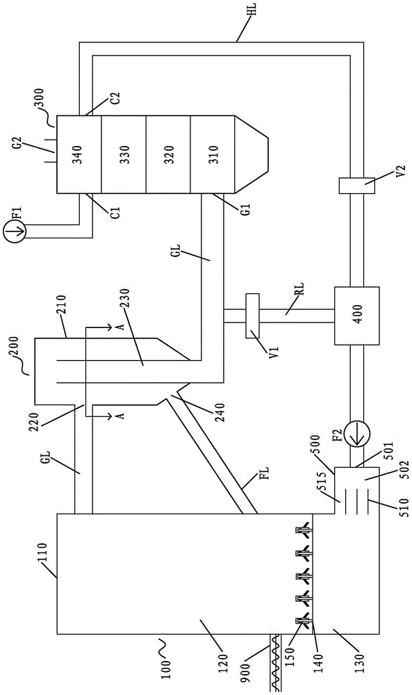
[0041] Please refer to figure 1 According to a non-limiting embodiment of the present invention, the energy-saving and environment-friendly circulating fluidized bed system includes: a fluidized bed 100, a flue gas separation device 200, a waste heat utilization device 300, and a flue gas pipeline GL.

[0042] Wherein, the fluidized bed 100 includes a fluidized bed body 110 and an air distribution plate 140 arranged inside the fluidized bed body 110, and the air distribution plate 140 divides the interior of the fluidized bed body 110 into a fluidized chamber 120 located above and a fluidized chamber 120 located below. The air chamber 130 is provided with several air caps 150 arranged on the air distribution plate 140 , so that the fluidizing air from the air chamber 130 can be sprayed into the fluidization chamber 120 by using the air caps 150 .

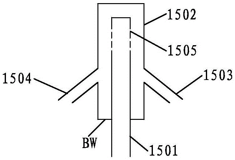
[0043] In this non-limiting embodiment, as figure 2 As shown, each air cap 150 includes an inner tube 1501, an outer tube 1502 s...


PUM


Abstract

The invention discloses an energy-saving environment-friendly circulating fluidized bed system. The circulating fluidized bed system comprises a fluidized bed, a smoke pipeline, a smoke separation device and a waste heat utilization device. The smoke separation device and the waste heat utilization device are arranged in the smoke flow direction of the smoke pipeline sequentially. The smoke separation device comprises a separator body, a high-temperature smoke inlet, a lower exhaust barrel and a material returning outlet. The high-temperature smoke inlet is formed in the side wall of the separator body and connected with the smoke pipeline. The lower exhaust barrel is perpendicularly arranged in an inner cavity of the separator body, a top inlet of the lower exhaust barrel is far away from the top wall of the separator body, and a bottom outlet of the lower exhaust barrel is connected with the waste heat utilization device through the smoke pipeline. The material returning outlet is formed in the bottom of the separator body and connected with a fluidized chamber through a material returning pipe. The waste heat utilization device comprises a dedusting smoke inlet, a low-temperature smoke outlet, a cold air inlet and a hot air outlet. The dedusting smoke inlet is connected with the bottom outlet of the lower exhaust barrel through the smoke pipeline. The low-temperature smoke outlet is connected to a chimney through the smoke pipeline. The cold air inlet is connected with a first fan through a cold air pipeline. The hot air outlet is connected with an air chamber through a hot air pipeline.

Description

technical field [0001] The invention relates to a boiler system, in particular to a circulating fluidized bed system. Background technique [0002] In the face of increasingly severe environmental problems and energy crises, the whole world is vigorously advocating energy conservation and emission reduction, especially for boiler-related industries with serious energy consumption and pollution. Factors that must be considered when designing such equipment. [0003] Taking the fluidized bed as an example, the temperature at the outlet of the flue gas usually reaches about 800 degrees Celsius. The flue gas contains a lot of smoke and dust. If the flue gas with soot is directly discharged into the environment, it will not only cause energy waste, but also cause waste of energy. It will also cause some damage to the environment. [0004] For example, Chinese patent 201320869949.6 discloses a circulating fluidized bed system for synergistic removal of PM2.5 and desulfurization,...

Claims


Application Information

Patent Timeline
Patent Type & Authority Applications(China)
IPC IPC(8): F23C10/08F23C10/26
CPCF23C10/08F23C10/26
Inventor 李树学宋长志邱燕飞
Owner GUANGDONG INST OF SPECIAL EQUIP INSPECTION
Why Eureka
Try Eureka