
Optical fiber F-P sensor vibration demodulation system based on polarization switching

A polarization switching and demodulation system technology, applied in instruments, measuring devices, and measuring ultrasonic/sonic/infrasonic waves, etc., can solve problems such as optical path imbalance, achieve good realizability, solve optical path imbalance problems, and eliminate problems Effect

Active Publication Date: 2016-06-01
NAT UNIV OF DEFENSE TECH
View PDF10 Cites 6 Cited by
  • Summary
  • Abstract
  • Description
  • Claims
  • Application Information

AI Technical Summary

Problems solved by technology

[0004] The present invention designs a polarization-switched F-P sensor vibration signal demodulation system, overcomes the unbalanced optical path problem in the traditional dual-wavelength demodulation system, and realizes two-way interference signals on the same light source, photodetector and the same optical path demodulation; at the same time, the present invention proposes a two-way signal demodulation method combining an ellipse fitting method and a differential cross multiplication algorithm, which can effectively avoid the error of the F-P sensor cavity length manufacturing process to the demodulation system. inaccuracy

Method used


Image

  • Optical fiber F-P sensor vibration demodulation system based on polarization switching
  • Optical fiber F-P sensor vibration demodulation system based on polarization switching
  • Optical fiber F-P sensor vibration demodulation system based on polarization switching

Examples


Embodiment Construction

[0031] In order to make the purpose, technical solution and advantages of the present invention clearer, the specific structure, principle and structural optimization process of the present invention will be further described in detail below in conjunction with specific embodiments and with reference to the accompanying drawings.

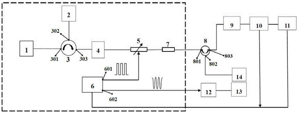
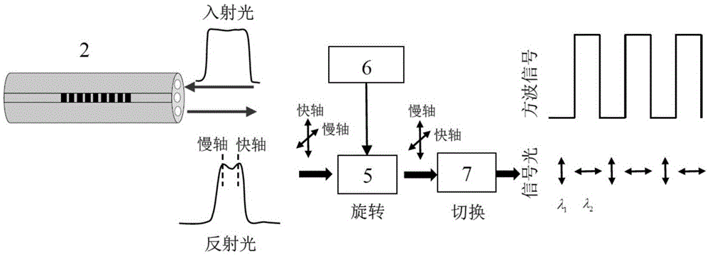
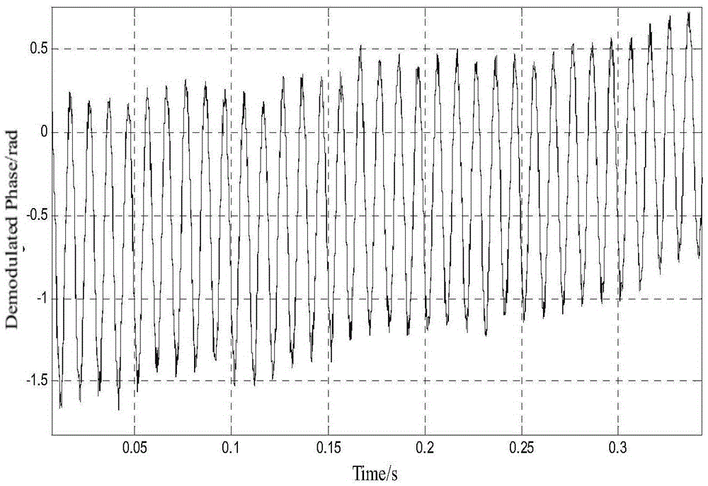
[0032] Such as figure 1 As shown, the present invention proposes a vibration signal demodulation system and method based on a polarization-switched optical fiber F-P sensor: the demodulation system consists of a wide-spectrum light source 1, a polarization-maintaining fiber grating 2, a polarization-maintaining circulator 3, and a polarization-maintaining erbium-doped Fiber amplifier 4, electro-optic modulator 5, signal generator 6, analyzer 7, circulator 8, electro-optic modulator 9, high-speed data acquisition card 10, computer 11, power amplifier 12, vibration table 13 and fiber optic F-P sensor 14 . Wherein by broadband light source 1, polariz...


PUM


Abstract

The invention relates to the optical fiber F-P sensor vibration signal demodulation system based on polarization switching and a demodulation method, belonging to the optical fiber sensing and the signal demodulation field. The device consists of a wide spectrum light source, a polarization-preserving fiber grating, a polarization-preserving circulator, a polarization-preserving er-doped optical fiber amplifier, an electro-optical modulator, a signal generator, an analyzer, a circulator, an electro-optical modulator, a high speed data collection card, a computer, a power amplifier, a vibration table and an optical fiber F-P sensor. The invention overcomes the problem that the optical path is imbalance in the traditional dual-wavelength demodulation system and realizes two-path interference signal demodulation on same light source, the photoelectric detector and on the same light path. In the mean time, the invention provides a two-path signal demodulation method combining an ellipse fitting alogrithm and a differential cross multiplication algorithm. The two-path signal demodulation method can effectively avoid the inaccuracy of the demodulation system which is caused by the F-P sensor cavity long manufacture technology.

Description

technical field [0001] The invention relates to a vibration signal demodulation system and demodulation method of an optical fiber F-P sensor based on polarization switching, belonging to the field of optical fiber sensing and signal demodulation. Background technique [0002] When external physical quantities (such as displacement, stress and temperature, etc.) are applied to a fiber optic Fabry-Perot (F-P) sensor, the cavity length of the sensor will change, which will lead to changes in the output interference phase signal. Therefore, interferometric phase signals are easily affected by external physical parameters, and phase signal demodulation is a major technical core of current demodulation technology. The demodulation of the interferometric sensor is also based on the solution of the phase. At present, researchers in related fields have proposed two methods to demodulate the phase signal: one method is based on the theory of white light interference, but the origina...

Claims


Application Information

Patent Timeline
Patent Type & Authority Applications(China)
IPC IPC(8): G01H9/00
CPCG01H9/004
Inventor 罗洪夏霁王付印熊水东张振慧曹春燕王建飞
Owner NAT UNIV OF DEFENSE TECH
Learn More