Eureka AIR delivers breakthrough ideas for toughest innovation challenges, trusted by R&D personnel around the world.

Photovoltaic intelligent charging control device

A technology for intelligent charging and control devices, applied in circuit devices, battery circuit devices, current collectors, etc., can solve problems such as unfavorable system efficiency, inability to ensure that photovoltaic cells work at the maximum power point, etc., and achieve the effect of improving utilization.

Inactive Publication Date: 2016-06-01
JIANGSU LVYANG ELECTRONICS INSTR GROUP
View PDF4 Cites 1 Cited by
  • Summary
  • Abstract
  • Description
  • Claims
  • Application Information

AI Technical Summary

Problems solved by technology

At present, the traditional solar photovoltaic charging method does not use a DC / DC converter between the photovoltaic cell and the battery, and directly uses an integrated circuit or a dedicated chip to charge the battery, which can save the DC / DC converter and improve the main circuit. Efficiency, however, since the operating voltage of the photovoltaic cell is positioned at the charging voltage point of the battery, it cannot be guaranteed that the photovoltaic cell will work at the maximum power point, which is not conducive to the improvement of the efficiency of the entire system

Method used


Image

  • Photovoltaic intelligent charging control device
  • Photovoltaic intelligent charging control device
  • Photovoltaic intelligent charging control device

Examples


Embodiment Construction

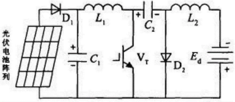
[0011] The photovoltaic intelligent charging control device of the present invention includes a photovoltaic cell array, a power source E d , Photovoltaic array and power supply E d Diode D1, inductor L1, capacitor C2, inductor L2 are connected in series between them. The anode of diode D1 is connected to the photovoltaic cell array, the cathode of diode D1 is connected to inductor L1, the inductor L1 is connected to the anode of capacitor C2, and the cathode of capacitor C2 is connected to inductor L2. Connect the other end of the inductor L2 to the power supply E d The cathode of the diode D1 and the power supply E d There is a capacitor C1 between the positive pole of the capacitor C2, the positive pole of the capacitor C2 and the power supply E d There is a switch tube Vr between the positive pole of the capacitor C2 and the power source E d A diode D2 is provided between the anode of the device.

[0012] Its working principle is as follows:

[0013] First make two assumptions: ...


PUM


Abstract

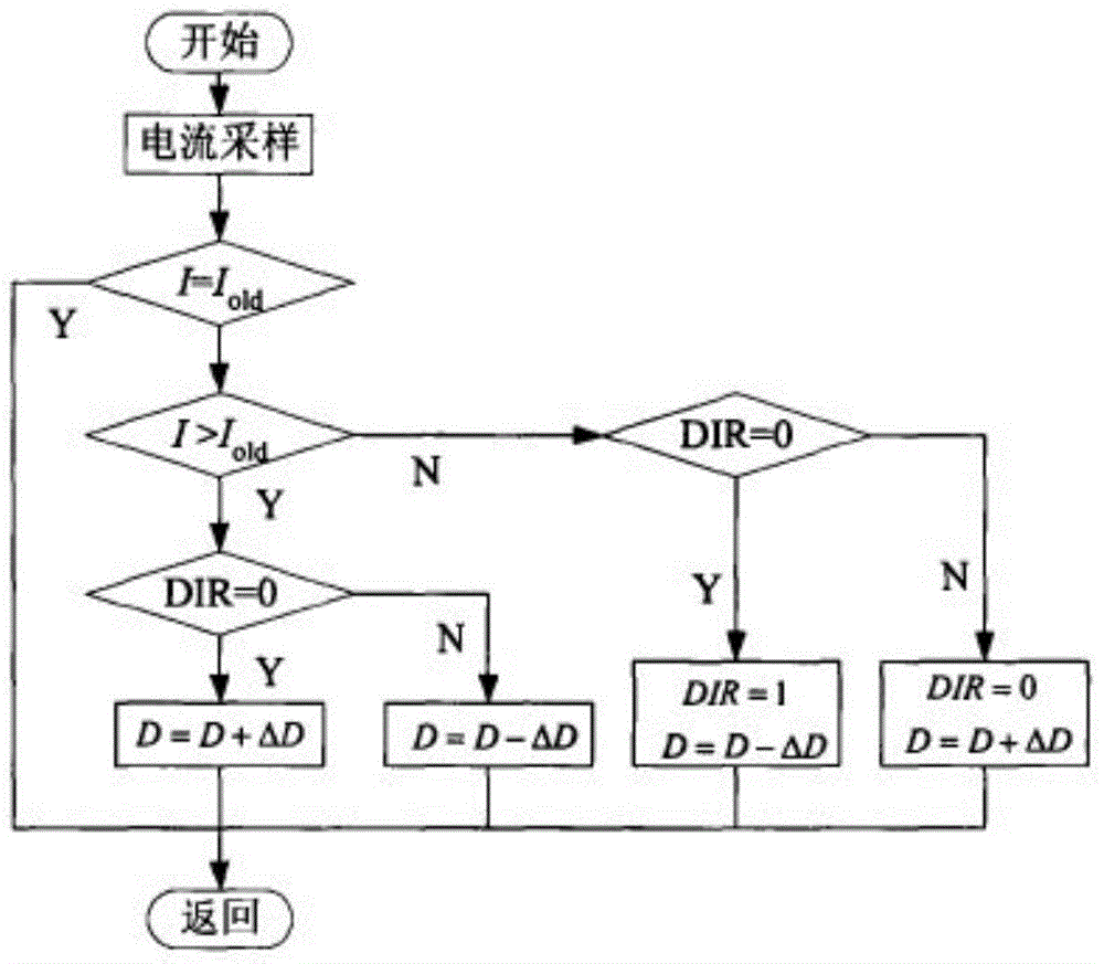
The invention belongs to the technical field of new energy and specifically relates to a photovoltaic intelligent charging control device. The photovoltaic intelligent charging control device comprises a photovoltaic cell array and a power supply Ed. A diode D1, an inductor L1, a capacitor C2 and an inductor L2 are serially connected between the photovoltaic cell array and the power supply Ed in sequence. An anode of the diode D1 is connected with the photovoltaic cell array, a cathode of the diode D1 is connected with the inductor L1. The inductor L1 is connected with an anode of the capacitor C2. A cathode of the capacitor C2 is connected with the inductor L2, and the other end of the inductor L2 is connected with a cathode of the power supply Ed. A capacitor C1 is arranged between the cathode of the diode D1 and an anode of the power supply Ed. A switch tube Vr is connected between the anode of the capacitor C2 and the anode of the power supply Ed. A diode D2 is arranged between the cathode of the capacitor C2 and the anode of the power supply Ed. According to the invention, multiplication operation is not needed, and the photovoltaic intelligent charging control device has the advantages the algorithm is simple and the influences of environment factors are small, so that the cost of the system is further lowered, and the operation load of a single-chip microcomputer is reduced.

Description

Technical field [0001] The invention belongs to the technical field of new energy, and specifically relates to a photovoltaic intelligent charging control device. Background technique [0002] Saving energy and protecting the environment have become necessary conditions for human sustainable development. People's attention is turning to the utilization and development of renewable energy. Among them, solar power generation has become a research focus in recent years. Photovoltaic charging systems generally include solar cells, solar controllers and batteries. Solar cell power generation is affected by climatic conditions, and its output power changes with changes in ambient temperature and light intensity, and has a nonlinear characteristic. Under certain climatic conditions, solar cells have the characteristics of flow but can work at different output voltages. Only when a certain output voltage value is the optimal output voltage value, the output power of the solar cell can r...

Claims


Application Information

Patent Timeline
Patent Type & Authority Applications(China)
IPC IPC(8): H02J7/00
Inventor 窦俊宋云衢
Owner JIANGSU LVYANG ELECTRONICS INSTR GROUP
Why Eureka
Eureka Blog
Learn More