Timing sequence power supply type wheel hub electric device and driving and braking method thereof
An electric device and sequential current technology, which is applied in the direction of motor control, electric motor/converter plug, electrical components, etc., can solve the problems of low cost performance, increased wheel hub weight, low weight/volume ratio power, etc., and improve the use efficiency , reduce the accumulated heat when energized, reduce the effect of energized heat accumulated
- Summary
- Abstract
- Description
- Claims
- Application Information
AI Technical Summary
Problems solved by technology
Method used
Image

Examples
Embodiment 1
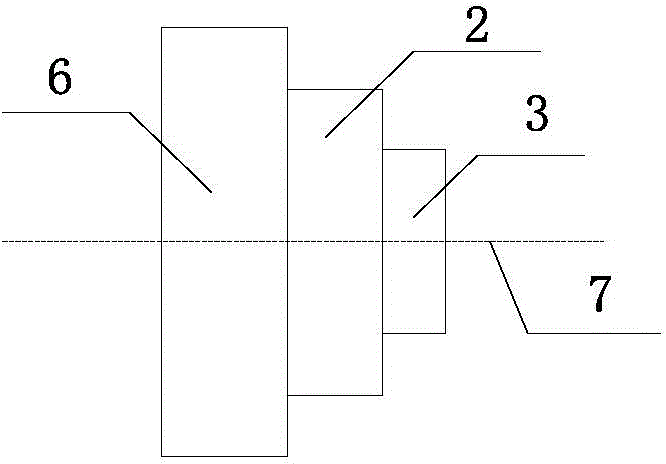
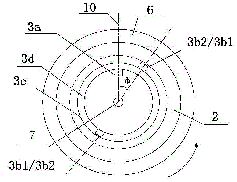
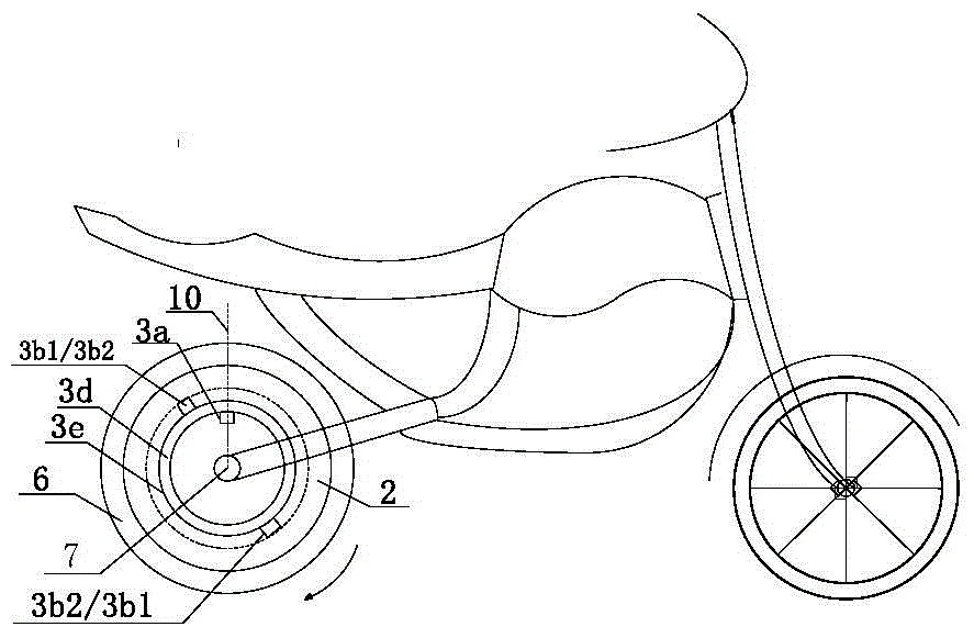
[0097] A hub electric device for an electric two-wheeled vehicle with a front and rear wheel structure, which is selected as Figure 1c Shown vehicle frame 4, the circumference of wheel 5 is 1000mm, and battery pack 8 selects lithium iron phosphate battery to be installed in the inside of vehicle frame; Hub electric device is located at the rear wheel of car. The coaxial rotating body 3e of the electric device 3 is a ring-shaped titanium-aluminum alloy ring with a rotating shaft and a circumference of 300mm. The outer edge of the alloy ring is fixedly connected with a rotor unit 3b, and the mechanical device that is fixedly connected with the fixed shaft inside the alloy ring Install a stator unit 3a; the coaxial rotating body 3e is coaxially installed with the hub 6, and a deceleration / torque conversion device 2 composed of several gears is arranged in between, and the deceleration / torque conversion device 2 realizes the connection with the hub 6 Mechanical transmission, the ...
Embodiment 2
[0104] Change the sequential current of the power supply modulator in Embodiment 1 to: T 1 The power-on time domain is set to a constant current corresponding to two periods of time and intensity, and the characteristic is the current I in the last 1 / 3 time 2 / A is the current intensity I in the first 2 / 3 time 1 / A half; the working logic of the power modulator is adjusted as follows: when the winding of the stator unit starts to be energized, the power modulator within 5s with I 1 Intensity 12A (corresponding to I 2 6A) as the reference, corresponding to the current sequence of the rotation cycle of the coaxial body, which automatically increases the output intensity by 1% every next cycle, and the relative ratio of the two power-on time domains is 2:1; wait for the drive control device from the 6th second Next step work instruction: if the drive control device 9a has no input command, the power modulator sleeps; if the command given by the drive control device is to accele...
Embodiment 3
[0107] On the basis of Embodiment 2, the power-on program of the power supply modulator is optimized: the T 1 The power-on time domain is set to 5 stages of current with the same power-on time but the current intensity decreases regularly, and the power-on intensity of the 5 stages is according to K*I 1 The linear relationship of / A decreases step by step, and the decrease coefficient K is 0.73, that is, when the initial current intensity of the 5-stage energization time is 12.0A, T 1 The current intensity within the sequence automatically decreases in the order of 12.0A, 8.8A, 6.4A, 4.7A, and 3.4A. The design of power-on program logic using conventional electronic circuits to achieve control is more complicated, and the manufacturing cost is also higher. The power modulator is replaced by mature pulse digital technology. .
[0108] The core module of the power modulator includes a conventional CPU and a drive module with a design power of 500W, and its detailed working logi...
PUM
| Property | Measurement | Unit |
|---|---|---|
| Perimeter | aaaaa | aaaaa |
Abstract
Description
Claims
Application Information
 - R&D
- Intellectual Property
- Life Sciences
- Materials
- Tech Scout
- Unparalleled Data Quality
- Higher Quality Content
- 60% Fewer Hallucinations
Browse by: Latest US Patents, China's latest patents, Technical Efficacy Thesaurus, Application Domain, Technology Topic, Popular Technical Reports.
© 2025 PatSnap. All rights reserved.Legal|Privacy policy|Modern Slavery Act Transparency Statement|Sitemap|About US| Contact US: help@patsnap.com