Battery system and battery module

A battery module and battery system technology, applied in the direction of battery/fuel cell control devices, batteries, secondary batteries, etc., can solve the problem of pressure drop in the refrigeration cycle and achieve uniform temperature

Active Publication Date: 2016-06-01
BAYERISCHE MOTOREN WERKE AG
View PDF7 Cites 5 Cited by
  • Summary
  • Abstract
  • Description
  • Claims
  • Application Information

AI Technical Summary

Problems solved by technology

However, the problem arises here that at low ambient temperatures the differential pressure in the refrigeration circuit drops, so that the mass flow of the refrigerant is not sufficient to cool the battery system and / or the battery modules sufficiently.

Method used


Image

  • Battery system and battery module
  • Battery system and battery module
  • Battery system and battery module

Examples


Embodiment Construction

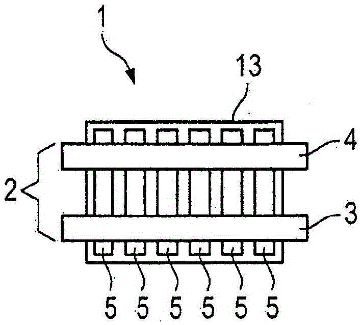
[0026] figure 1 A battery module 1 according to an exemplary embodiment of the invention is shown. The battery module 1 comprises a battery cell body 13 in which the individual battery cells 5 of the battery module 1 are arranged. Each battery cell 5 is used to store and output electrical energy. Since power losses always occur as heat both when storing electrical energy and when delivering electrical energy, the individual battery cells 5 must be cooled in order to avoid overheating of the battery cells 5 . Otherwise, overheating of the battery cells 5 would significantly reduce the service life and performance of the battery cells 5 and thus of the battery module 1 .

[0027] The battery module 1 has a cooling device 2 for cooling the battery cells 5 . The cooling device 2 includes a first pipeline 3 and a second pipeline 4 . A fluid can be conducted inside the first line 3 and the second line 4 , which fluid receives thermal energy from the battery cells 5 . Preferably...


PUM


Abstract

The invention relates to a battery module having a cooling apparatus, comprising at least one first line and at least one second line, wherein the first line and the second line conduct a fluid and absorb heat from cells of the battery module and transfer said heat to the fluid, wherein the first line and the second line extend perpendicular to the cells of the battery module, the first line and the second line are arranged parallel to one another, a flow direction of the fluid in the first line is opposite a flow direction of the fluid in the second line.

Description

technical field [0001] The invention relates to a battery module with which electric energy can be stored. Furthermore, the invention relates to a battery system which in particular comprises a plurality of such battery modules. Finally, the invention relates to a vehicle comprising a battery module or a battery system. Background technique [0002] In particular, battery systems are used in electric vehicles and hybrid vehicles in order to be able to supply electrical energy to the electrical components of the vehicle. In order to ensure range, service life and power availability, defined temperature management of the battery system and battery modules is required. In this case, it is necessary to keep the temperature differences between the individual battery modules or the individual battery cells of the battery modules as small as possible. [0003] In order to maintain a defined temperature, various solutions are possible. On the one hand, the battery modules can be...

Claims


Application Information

Patent Timeline
Patent Type & Authority Applications(China)
IPC IPC(8): H01M2/10B60H1/00B60L11/18H01M10/613H01M10/617H01M10/625H01M10/6556H01M10/656H01M10/6567H01M10/6569H01M50/209H01M50/24H01M50/249
CPCH01M10/625H01M10/6556H01M10/6569H01M10/6567H01M10/617H01M10/613H01M10/656B60L2240/545B60L58/26H01M10/6568H01M2220/20Y02T10/70Y02E60/10H01M50/249H01M50/209H01M50/24
Inventor F·艾内格N·弗拉奥M·休伯S·西林S·魏莱德A·林
Owner BAYERISCHE MOTOREN WERKE AG
Why Eureka
Try Eureka