
Transfer printing equipment and coater

A technology of equipment and transfer plate, applied in rotary printing presses, printing presses, transfer printing and other directions, can solve the problems of printing deviation, product defects, etc., to improve contrast, avoid extension deformation and sliding, and ensure no deviation. Effect

Inactive Publication Date: 2016-06-08
BOE TECH GRP CO LTD +1
View PDF13 Cites 13 Cited by
  • Summary
  • Abstract
  • Description
  • Claims
  • Application Information

AI Technical Summary

Problems solved by technology

[0003] In order to solve the above problems, the present invention provides a transfer printing device and a coating machine, which are used to solve the problems of stretching, deformation and sliding of the transfer printing plate in the prior art, resulting in printing deviation and defective final products

Method used


Image

  • Transfer printing equipment and coater
  • Transfer printing equipment and coater
  • Transfer printing equipment and coater

Examples


Embodiment 1

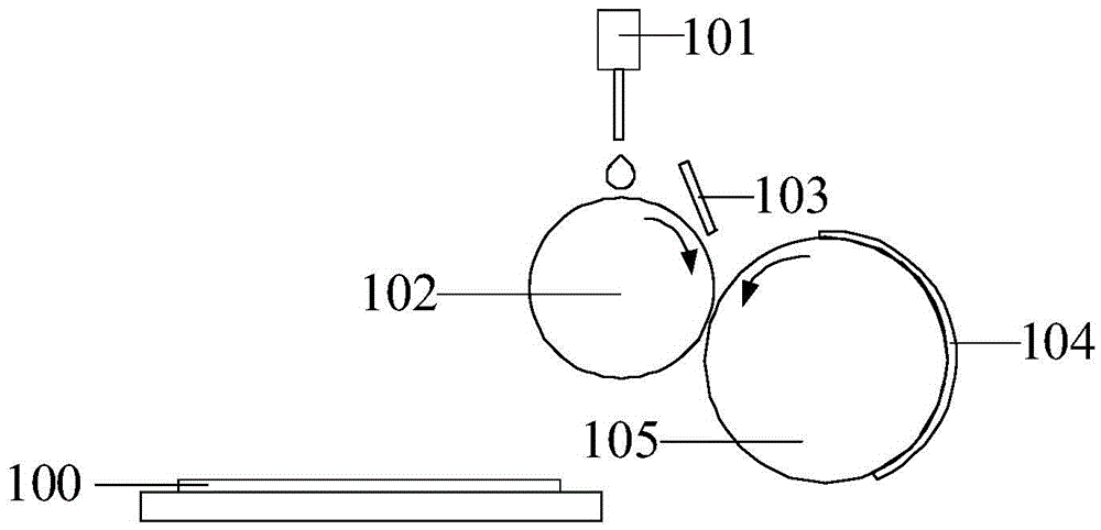
[0033] The alignment film in the display panel makes the liquid crystal molecules arrange in an orderly manner. Under the action of the electric field, the liquid crystal molecules rotate at a corresponding angle, so that the backlight can pass through the polarizer through the rotating liquid crystal to achieve the display effect. figure 1 Schematic diagram of the coating system. Such as figure 1 As shown, the specific implementation of the alignment film coating process is as follows: the dispenser 101 discharges polyimide (Polyimide, PI for short) onto the anilox roller 102, and the doctor blade 103 uniformly coats the discharged polyimide on the screen. Texture roller 102. The anilox roller 102 prints polyimide onto a pre-patterned transfer printing plate (Asai Kasai Photosenstive Resin Plate, APRPlate for short). The printing roller 105 transfers the polyimide onto the glass substrate 100 through the transfer plate 104 fixed thereon, and finally forms an alignment film....

Embodiment 2

[0043] The present invention provides a coating machine, including the transfer printing device provided in Embodiment 1. For details, please refer to the description of Embodiment 1, which will not be repeated here.

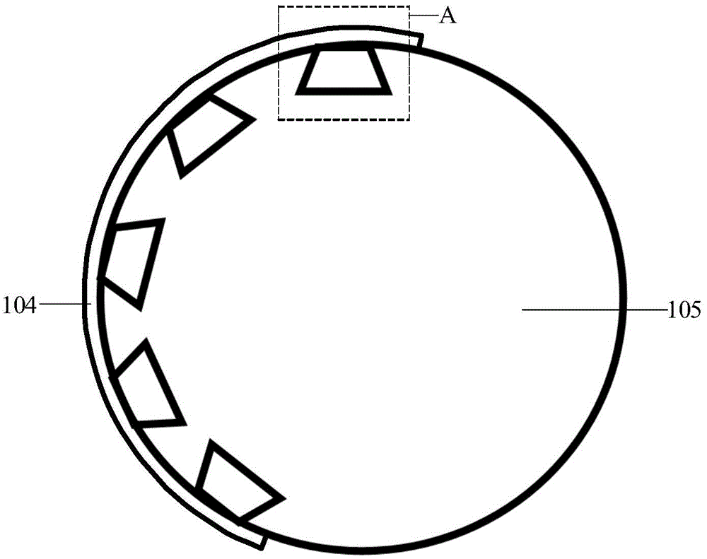
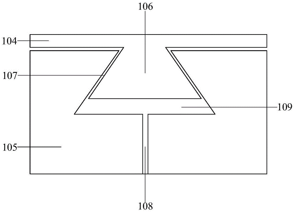
[0044] In the coating machine provided in this embodiment, the transfer device includes a transfer plate and a printing roller, and the protrusions of the transfer plate cooperate with the grooves of the printing roller to fix the transfer plate and the printing roller. The printing roller can not only solve the alignment problem between the transfer printing plate and the printing roller, but also optimize the orientation and uniformity of the alignment film by adjusting the ability of the transfer printing plate to accommodate polyimide, Thereby, the orderliness of the arrangement of the liquid crystal molecules is enhanced, and finally the contrast of the display panel is improved. In addition, the technical solution provided in this embodiment allows the tra...


PUM


Abstract

The invention discloses transfer printing equipment and a coater. The transfer printing equipment comprises an Asai Kasai photosensitive resin plate (APR plate) and a printing roller, wherein a bump of the APR plate is mutually matched with a groove of the printing roller for fixing the APR plate and the printing roller, so that the aligning problem of the APR plate and the printing roller can be solved, the capacity of accommodating polyimide of the APR plate can be regulated, and the orientation and the uniformity of an orientation film are optimized, and therefore, the order of liquid crystal molecular arrangement is strengthened, and the contrast ratio of a display panel is finally improved. Besides, according to the technical scheme provided by the invention, a vacuum adsorption mode is adopted to replace a mechanical fixing mode for firmly adsorbing the APR plate onto the printing roller, so that the APR plate does not generate extension deformation and sliding under the action of printing external force. The technical scheme provided by the invention can prevent the APR plate from generating extension deformation and sliding, and production printing is guaranteed to not deviate, so that the product quality is guaranteed to the greatest extent.

Description

technical field [0001] The invention relates to the field of display technology, in particular to a transfer printing device and a coating machine. Background technique [0002] The transfer printing plate of the existing coating machine is fixed on the printing roller by mechanical buckling. When the coating machine is producing and printing, due to the external force of the anilox roller and the printing pressure of the base, the transfer printing plate will Stretching and sliding occur, causing printing to deviate and ultimately resulting in defective products. Contents of the invention [0003] In order to solve the above problems, the present invention provides a transfer printing device and a coating machine, which are used to solve the problems in the prior art that the transfer printing plate is stretched, deformed and slipped, resulting in printing deviation and defective final products. [0004] To this end, the present invention provides a transfer printing dev...

Claims


Application Information

Patent Timeline
Patent Type & Authority Applications(China)
IPC IPC(8): B41F16/00B41F27/12
CPCB41F16/00B41F27/12B41F17/26B41F27/02B41F27/10B41F27/1262C23C14/22
Inventor 井杨坤刘满成桑胜光
Owner BOE TECH GRP CO LTD
Learn More