

Optical component and timepiece
A technology for optical components and clocks, applied in optical components, clocks, optics, etc., to achieve the effect of excellent visibility and excellent light transmittance
- Summary
- Abstract
- Description
- Claims
- Application Information
AI Technical Summary
Problems solved by technology
Method used
Image

Examples
no. 1 Embodiment approach
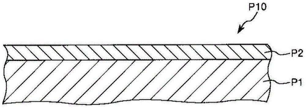
[0036] figure 1 It is a cross-sectional view schematically showing the first embodiment of the optical component of the present invention.
[0037] Such as figure 1 As shown, the optical component P10 of the present embodiment includes a base material P1 and a titanium oxide layer P2 mainly composed of titanium oxide. In addition, the titanium oxide layer P2 contains one or two or more elements selected from the group consisting of Nb, Si, Zr, Ta, Al, and Hf as subcomponents.
[0038] With such a configuration, the optical component P10 as a whole can ensure sufficient translucency and exhibit an antistatic function. In other words, the titanium oxide layer P2 can function as an antistatic film. As a result, for example, adhesion of dirt such as dust due to static electricity can be prevented, and the optical component P10 can stably exhibit the inherent optical characteristics.
[0039] It should be noted that this excellent effect is obtained by the titanium oxide layer ...
no. 2 Embodiment approach
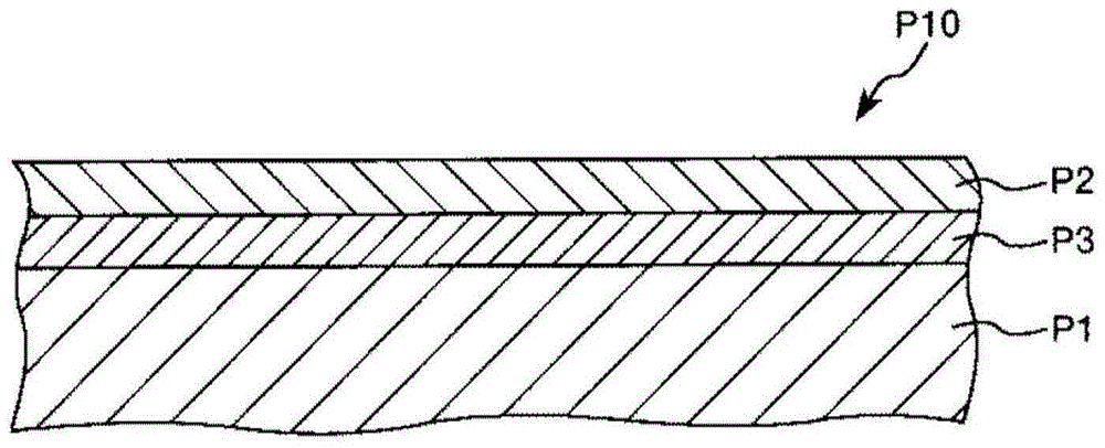
[0071] figure 2 It is a cross-sectional view schematically showing a second embodiment of the optical component of the present invention. In the following description, differences from the above-described embodiment will be mainly described, and descriptions of the same matters will be omitted.
[0072] Such as figure 2 As shown, the optical component P10 of this embodiment includes a base material P1, a titanium oxide layer P2, and an underlayer P3. That is, it has the same structure as that of the above-mentioned embodiment except having the base layer P3 between the base material P1 and the titanium oxide layer P2.
[0073] In this way, by having the underlayer P3, for example, the adhesion between the base material P1 and the titanium oxide layer P2 (adhesion through the underlayer P3) can be made particularly excellent, and the durability and reliability of the optical component P10 can be particularly improved. excellent.
[0074] As a constituent material of the b...
Embodiment 1
[0129] A cover glass as an optical component was manufactured by the method shown below.
[0130] First, a plate material (glass plate) made of sapphire glass is prepared as a base material (base material preparation process), and necessary parts are cut and polished. The base material after cutting and grinding was approximately disc-shaped, and had a size of diameter: 30 mm×thickness: 1 mm.
[0131] Next, an ultraviolet irradiation treatment of irradiating ultraviolet rays having a wavelength of 248 nm was performed on the surface of the substrate on which the titanium oxide layer was to be formed.
[0132] Next, by using titanium dioxide (TiO 2 ) and niobium oxide (Nb 2 o 5 ) was ion beam-assisted vapor deposition as a vapor deposition source to form a titanium oxide layer on the base material (titanium oxide layer forming step) to obtain a cover glass as an optical component.
[0133] ion beam assisted evaporation on O 2 Gas flow rate: 50sccm, acceleration voltage: 70...
PUM
| Property | Measurement | Unit |
|---|---|---|
| thickness | aaaaa | aaaaa |
| thickness | aaaaa | aaaaa |
| thickness | aaaaa | aaaaa |
Abstract
Description
Claims
Application Information