
Air purifying machine

A technology of air purifiers and outer casings, which is applied to chemical instruments and methods, separation methods, filtration and separation, etc., which can solve the problems of water turbidity, poor air purification effect, and affect the effect of air purification, so as to achieve saving Effects of energy, intensifying Brownian motion, and enhancing purification effect

Active Publication Date: 2016-06-15
贵州合心慧能科技有限公司
View PDF3 Cites 6 Cited by
  • Summary
  • Abstract
  • Description
  • Claims
  • Application Information

AI Technical Summary

Problems solved by technology

Although this solution can remove the water vapor carried in the air, it does not have a good impact on the air purification effect
[0003] In addition, when using water spray to filter and purify the air, the dust in the air will be brought into the water, which will gradually make the water turbid, requiring more frequent water changes, otherwise it will affect the effect of air purification

Method used


Image

  • Air purifying machine
  • Air purifying machine
  • Air purifying machine

Examples


Embodiment 1

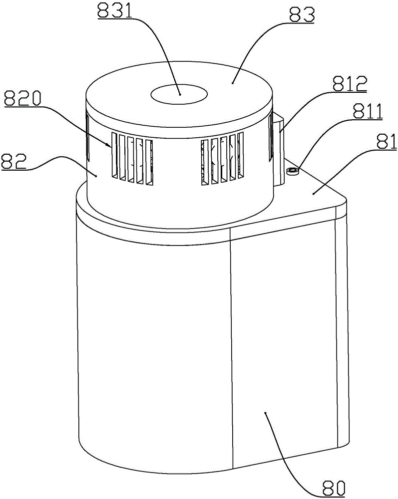
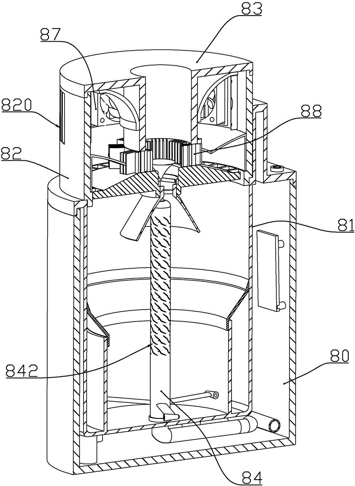
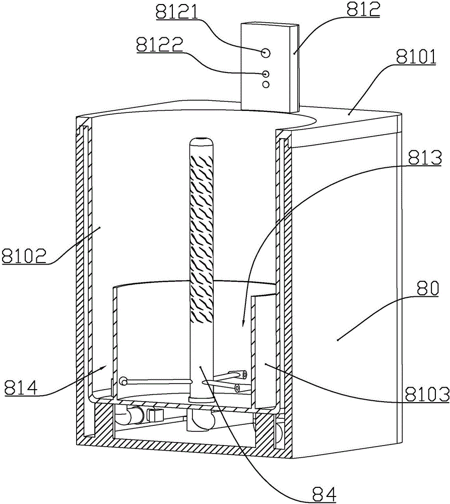
[0063] according to Figure 1 to Figure 9 As shown, the present embodiment is an air purifier, including an outer casing 80 in the shape of a quadrilateral tank body, and an inner casing 81 loaded into the outer casing from top to bottom; the outer casing has 3 The vertical side wall surface and a semicircular arc surface in turn; the inner casing includes an upper connecting plate 8101 that is connected with the upper opening of the outer casing, and a cylindrical water bucket 8102 integrally connected to the upper connecting plate. The water bucket and the semicircular surface on the outer casing have the same center; the bottom of the water bucket is formed with an annular partition 8103, and the inside of the water bucket is located on the inner periphery of the annular partition to form a water storage bucket 813, and the inside of the water bucket is located on the annular partition A waste water storage bucket 814 is formed on the outer periphery; an inverted tapered wa...

Embodiment 2

[0082] On the basis of embodiment 1, this embodiment has also carried out the following improvements: Figure 10 to Figure 16 As shown, the filter P includes a cylinder body 2 and a cover body 1 connected by threads, and a ceramic filter element assembly 3 installed in the space between the cylinder body 2 and the cover body 1 .

[0083] The two sides of the cover body are respectively formed with water inlet and outlet interfaces 11 and water outlet interfaces 12; the inner bottom of the cover body is integrally formed with a water outlet joint 14 in the middle, and the water outlet joint is connected with the water outlet interface; A water inlet 111 connected to the water inlet and outlet.

[0084] The ceramic filter element assembly 3 includes a circular tube-shaped ceramic filter element 31 and a first sealing head 32 and a second sealing head 34 fixedly connected to both ends of the ceramic filter element respectively. The water outlet connector 33, the outer wall of th...

Embodiment 3

[0101] This embodiment also has the following improvements on the basis of Embodiment 2. The raw material components of the ceramic filter element include: 80% diatomite, 6% calcium carbonate, 4% kaolin, 10% activated carbon, the above-mentioned The raw materials are crushed to 160-180 meshes and then mixed. After mixing evenly, water is added to make mud, and gypsum molds are used to make mud billets, which are sintered to form finished products. The ceramic filter element is in the shape of a circular tube, the thickness of the ceramic filter element is 5-15 mm, and the pore diameter of the micropores on the ceramic filter element is 0.4-0.8 μm.

[0102] Since the filter is only used to filter out particulate impurities in the water, the filter requirements for drinking water are much lower than that of drinking water, so the ceramic filter element has a larger pore size than the ceramic filter element of the drinking water filter, and the filtration flow rate is larger. The...


PUM

PropertyMeasurementUnit
Thicknessaaaaaaaaaa
Pore diameteraaaaaaaaaa

Abstract

The invention discloses an air purifying machine. The air purifying machine comprises an outer machine casing, and an inner machine casing which is mounted in the outer machine casing; the inner machine casing comprises a cylindrical water barrel; an annular partition plate is formed in the bottom of the water barrel; a water storage barrel is formed in the inner periphery of the annular partition plate in the water barrel; a waste water storage barrel is formed in the outer periphery of the annular partition plate in the water barrel; an inverted conical water guide plate is mounted on the annular partition plate; the lower end of the water guide plate extends to the inner side of the annular partition plate; the upper end of the water guide plate is adhered to the inner wall of the water barrel; a water curtain water inlet joint is formed in the center of the bottom of the water storage barrel; a water pumping joint is formed at the position, which is different from the position of the water curtain water inlet joint, at the bottom of the water storage barrel; a waste water joint is formed at the bottom of the waste water storage barrel; a filter and a water pump are also mounted in the space between the outer machine casing and the inner machine casing; a water spraying column is rotatably connected to the upper part of the water curtain water inlet joint in a sleeving manner; a plurality of groups of water spraying holes are formed in the part, higher than the annular partition plate, of the side wall of the water spraying column in an axial direction at equal intervals. The air purifying machine has a good effect on purifying air, and is energy-saving and environment-friendly.

Description

technical field [0001] The invention belongs to the field of air purifiers, in particular to an air purifier. Background technique [0002] The Chinese patent application with the patent application number CN201410208170.9 discloses an air purification device that mainly uses water showering and is supplemented by semiconductor cooling and heating effects. It uses a set of "P-N" junction semiconductor devices (semiconductor cooling chips) to The filtered air is condensed to liquefy the water vapor carried by the air when it is filtered, and then the heat surface of the semiconductor cooling chip heats the air to restore it to its original temperature. Although this solution can remove the water vapor carried in the air, it cannot have a good impact on the air purification effect. [0003] In addition, when using water spray to filter and purify the air, the dust in the air will be brought into the water, which will gradually make the water turbid, requiring more frequent wa...

Claims


Application Information

Patent Timeline
IPC IPC(8): B01D47/06B01D33/06B01D33/46
CPCB01D29/11B01D29/6415B01D33/06B01D33/461B01D47/06B01D47/08B01D2247/04B01D2247/10
Inventor 喻文武贾新奎
Owner 贵州合心慧能科技有限公司
Learn More