Planar passive micromixer

A mixer and passive technology, applied in mixers, chemical instruments and methods, dissolution, etc., can solve problems that are not conducive to mass production and large-scale application, high production cost, complex structure, etc., and achieve simple structure and easy processing , low-cost effect

Active Publication Date: 2016-06-15
SUZHOU WENHAO MICROFLUIDIC TECH CO LTD
View PDF3 Cites 12 Cited by
  • Summary
  • Abstract
  • Description
  • Claims
  • Application Information

AI Technical Summary

Problems solved by technology

However, the structure of this type of micro-mixer is mostly three-dimensional structures such as slope-shaped, inclined-shaped, and ladder-shaped. Compared with planar mixers, its structure is more complicated and processing is more difficult.
At the same time, the production cost is high, which is not conducive to mass production and large-scale application

Method used


Image

  • Planar passive micromixer
  • Planar passive micromixer
  • Planar passive micromixer

Examples


Embodiment 1

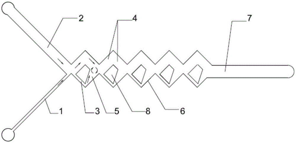
[0033] Such as figure 1 Shown, a kind of planar passive micro-mixer, the cross-section of the first inlet channel and the second inlet channel is rectangular, the first inlet channel 1 and the second inlet channel 2 are vertical, converging at the intersection of the mixing unit 6, The mixing unit 6 here is a cavity surrounded by quadrangular side walls. There is a stopper 8 in the mixing unit 6. The stopper 8 separates the mixing unit 6 into a first split channel 3, a second split channel 4 and a mixed flow channel. The cavity 5, the first flow channel 3 and the second flow channel 4 communicate with the intersection of the mixing unit 6, and the flow mixing cavity 5 communicates with the first flow channel 3 and the second flow channel 4 of the adjacent mixing unit. And it is located at the outlet of the mixing chamber 5 .

[0034] The cross section of the stopper 8 here is a right-angled trapezoid, and the mixed flow chamber 5 formed by the separation matches the shape of ...

Embodiment 2

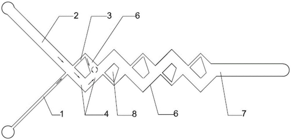
[0037] Such as figure 2 As shown, the second embodiment is basically similar to the first embodiment, but different from the first embodiment, the shape of the stopper 8 in each mixing unit 6 is the same, and the mixing unit 6 includes first alternately arranged The mixing unit and the second mixing unit; the stoppers in the first mixing unit are set differently from the stoppers in the second mixing unit. Of course, the arrangement direction can also be random, as long as the mixing chamber 5 of the mixing unit 6 communicates with the first flow channel 3 and the second flow channel 4 in the adjacent mixing unit 6, and is located at the outlet of the mixing unit 6, that is Can.

Embodiment 3

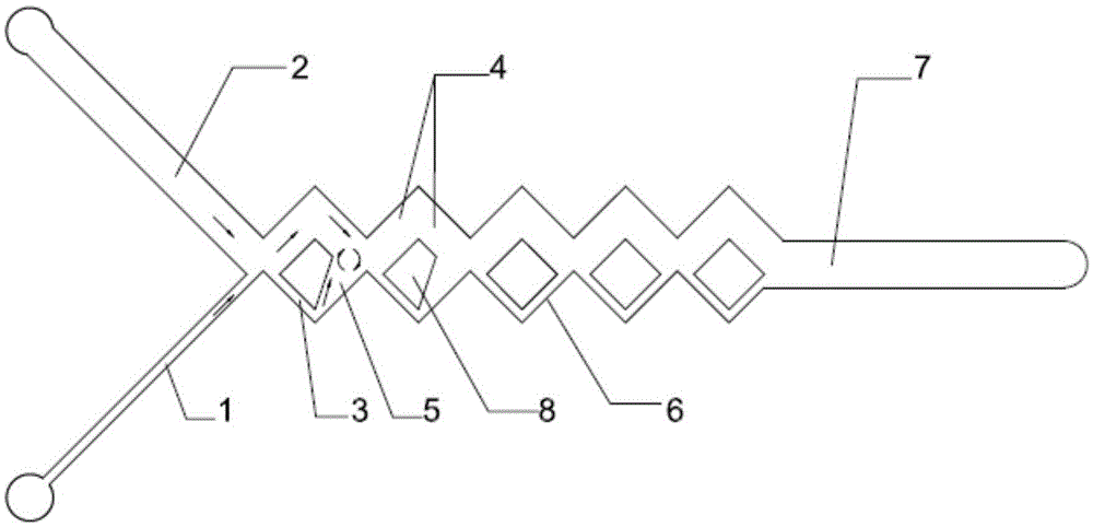
[0039] Such as image 3As shown, the third embodiment is basically similar to the first embodiment, but different from the first embodiment, the cross-section of some stoppers 8 is a right-angled trapezoid, and the cross-section of some stoppers 8 is a square, which are separated to form The mixed flow chamber 5 matches the shape of the stopper 8. When the cross section of the stopper 8 is a right-angled trapezoid, the mixed flow chamber 5 is a trapezoidal cavity, and the width of the mixed flow chamber gradually increases from the first flow channel to the second flow channel. widen. When the cross section of the block 8 is a square, the mixed flow chamber 5 is a rectangular cavity, and the width of the mixed flow chamber 5 is equal.

[0040] The shape of stopper 8 in each mixing unit 6 is different, and the cross section of stopper 8 is a right-angled trapezoid in the first mixing unit, and the cross-section of stopper 8 in the second mixing unit 6 is a right-angled trapezo...


PUM


Abstract

The invention discloses a planar passive micromixer.The planar passive micromixer comprises an inlet passage, an outlet passage and at least one mixing unit between the inlet passage and the outlet passage.Each mixing unit comprises a first flow distribution passage, a second flow distribution passage and a flow mixing cavity, wherein the first flow distribution passage and the second flow distribution passage are used for liquid flow distribution, the flow mixing cavity is used for mixing liquid flowing from the first flow distribution passage and the second flow distribution passage and communicated with the first flow distribution passage and the second flow distribution passage of the adjacent mixing unit or communicated with the outlet passage.According to Coada effects, the micromixer structurally leads a medium to form chaotic convection in a convection cavity, and mixing effects are remarkably improved.

Description

technical field [0001] The invention relates to the technical field of microfluidic chips, in particular to a planar passive micromixer. Background technique [0002] As an important part of microfluidic systems, micromixers are increasingly used in fields such as biological analysis, chemical synthesis and clinical testing due to their efficient and rapid mixing performance. When two or more fluids undergo chemical reactions, it is necessary to achieve rapid and effective mixing, so the micro-mixer is an important part of microfluidics. Since the channel structure of the microfluidic chip is on the order of microns, the fluid in the channel is usually at The state of laminar flow, so achieving rapid mixing of fluids at the microscale has also become crucial. Under different Reynolds numbers, the fluids in the channels are mixed through molecular diffusion and convective mixing. Although the former has extremely high mixing efficiency, it requires a long mixing time at low...

Claims


Application Information

Patent Timeline
Patent Type & Authority Applications(China)
IPC IPC(8): B01F13/00
CPCB01F33/3017B01F33/3034B01F33/3045B01F2101/23
Inventor 宋国庆聂富强
Owner SUZHOU WENHAO MICROFLUIDIC TECH CO LTD
Why Eureka
Try Eureka