An automatic bead discharge device suitable for narrow gap welding

An automatic row, narrow gap technology, applied in welding equipment, electrode support device, welding rod characteristics, etc., can solve the problems of large transmission gap of the welding torch rotating mechanism, large wear of the welding torch rotating transmission mechanism, and low control accuracy of the welding torch in place repeatedly. High repeatability in place, long service life, and the effect of improving service life

Active Publication Date: 2018-05-04
北京时代科技股份有限公司 +2
View PDF7 Cites 0 Cited by
  • Summary
  • Abstract
  • Description
  • Claims
  • Application Information

AI Technical Summary

Problems solved by technology

[0004] The existing welding bead device for narrow gap welding usually adopts the method of rigid shift fork or gear pair transmission. These methods usually have a large transmission gap of the welding torch rotation mechanism, low accuracy of welding torch repeat position control, large wear of the welding torch rotation transmission mechanism, and welding torch Rotating mechanism is close to the arc high temperature area, resulting in short service life and other disadvantages

Method used


Image

  • An automatic bead discharge device suitable for narrow gap welding
  • An automatic bead discharge device suitable for narrow gap welding
  • An automatic bead discharge device suitable for narrow gap welding

Examples


Embodiment Construction

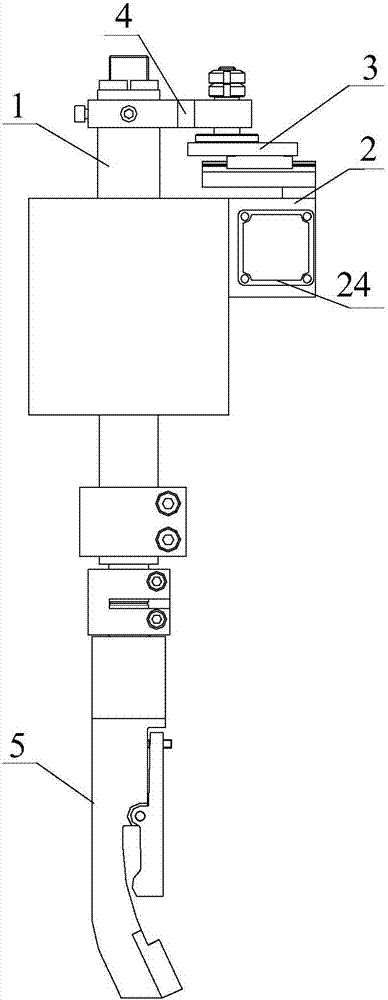
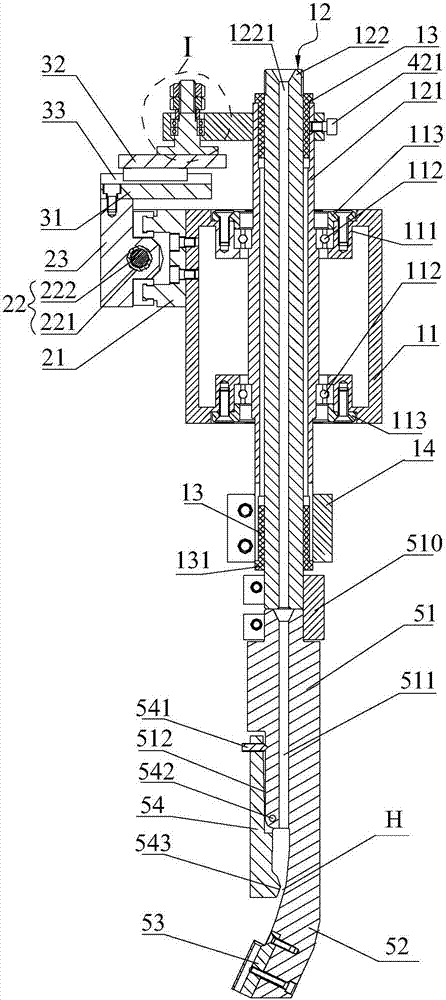
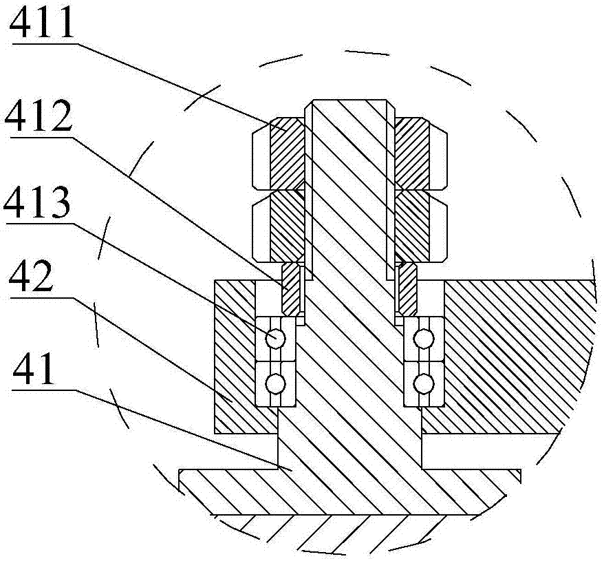
[0052]The invention proposes an automatic bead discharge device suitable for narrow gap welding, which includes: a gun angle rotating device, which is provided with a box body and a rotating rod for guiding welding wire, and the rotating rod can be rotated through The lower end of the box is connected with a welding torch; the transverse movement mechanism is fixed on the outside of the box through a transverse slide, and a horizontally placed horizontally placed between the two ends of the transverse slide Ball screw, the nut seat of the ball screw is equipped with a horizontal sliding table, one end of which is connected with the output shaft of a digital motor installed at one end of the horizontal sliding seat; the longitudinal follow-up mechanism includes a longitudinal sliding seat , a longitudinal slide and a longitudinal guide rail, the longitudinal slide is fixed on the upper end surface of the transverse slide, the longitudinal guide is mounted on the longitudinal sli...


PUM


Abstract

The invention discloses an automatic weld pass arrangement apparatus applicable to narrow gap welding. The automatic weld pass arrangement apparatus comprises a gun corner rotating apparatus, a transverse moving mechanism, a longitudinal following mechanism, and a rocker mechanism, wherein the gun corner rotating apparatus is provided with a box body and a rotating rod part; the rotating rod part is rotatably inserted in the box body; the lower end of the rotating rod part is connected with a welding gun; the transverse moving mechanism is fixedly arranged outside the box body by a transverse sliding seat; a ball screw horizontally placed in a transverse direction is mounted between two ends of the transverse sliding seat; a transverse sliding table is mounted on a nut bed of the ball screw; one end of the transverse sliding table is connected with an output shaft of a digital motor mounted at one end of the transverse sliding seat; the longitudinal following mechanism comprises a longitudinal sliding seat, a longitudinal sliding table and a longitudinal guide rail; the longitudinal sliding seat is fixedly arranged at the upper end face of the transverse sliding table; the longitudinal guide rail is mounted on the longitudinal sliding seat; the longitudinal sliding table can be connected to the longitudinal guide rail in a manner of horizontally moving in a longitudinal direction; the rocker mechanism is provided with a rocker strut and a rocker; the rocker strut is arranged on the longitudinal sliding table; one end of the rocker rotatably sleeves the rocker strut, and the other end of the rocker is connected with the upper end of the rotating rod part.

Description

technical field [0001] The invention belongs to the field of narrow-gap welding of medium-thick plates, and in particular relates to an automatic welding bead arrangement device suitable for narrow-gap welding with high repeat positioning accuracy and long service life. Background technique [0002] Narrow gap welding, that is, no groove or only a small angle groove is made before welding of thick plate butt joints, and a narrow and deep gap is left. The height of the entire weld completed by metal gas shielded welding or submerged arc welding High-efficiency welding method. At present, narrow gap welding is mainly used for the welding of circular seams and longitudinal seams of medium and thick plates in boilers, pressure vessels, chemical equipment and nuclear power manufacturing. It is suitable for carbon steel, low alloy steel, low temperature steel and pearlite. Heat-resistant steel and other materials. Compared with the corresponding traditional welding method, this m...

Claims


Application Information

Patent Timeline
Patent Type & Authority Patents(China)
IPC IPC(8): B23K9/173B23K9/28
CPCB23K9/173B23K9/28
Inventor 华爱兵鲍云杰胡志斌
Owner 北京时代科技股份有限公司
Why Eureka
Try Eureka