Spiral-flow type jammed cavitation device for breaking excess sludge

A technology of surplus sludge and swirling flow, which is applied in the direction of oxidation treatment of sludge, chemical instruments and methods, water/sludge/sewage treatment, etc., and can solve the problems of collapse, ring-type clogged cavitator and easy blockage, etc. , to achieve the effect of improving cavitation intensity, simple structure and high energy utilization rate

Active Publication Date: 2016-06-15
安徽明亮面业股份有限公司
View PDF9 Cites 4 Cited by
  • Summary
  • Abstract
  • Description
  • Claims
  • Application Information

AI Technical Summary

Problems solved by technology

The design of the swirling choked cavitator is based on the choked cavitation theory and the swirling jet theory. By designing a specific cavitator structure, the cavitation can be effectively collapsed and more cavitation can be induced by using the swirl nozzle. , which greatly improves the ability and efficiency of the cavitation effect and the mechanical shear force effect to synergistically break down the excess sludge, and at the same time solves the problem that the annular clogged cavitator is easy to block, so that the hydraulic cavitation technology is moving towards industrial applications. another big step on the road

Method used


Image

  • Spiral-flow type jammed cavitation device for breaking excess sludge
  • Spiral-flow type jammed cavitation device for breaking excess sludge
  • Spiral-flow type jammed cavitation device for breaking excess sludge

Examples


Embodiment Construction

[0022] 1) Implementation parameters of the present invention

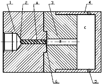
[0023] Such as figure 1 , the swirl body 1 and the choke body 3 are connected by bolts, the swirl core 2 and the swirl body 1 adopt a tight clearance fit, and there is a 0.4mm step 6 at the outlet end of the swirl core 2 for axial positioning, and the choke body 3 It is connected with the back pressure cover 4 with a cylindrical pin, and the swirl body 1 is connected with the external water supply pipe with threads. Each connection part adopts the corresponding sealing form. The equivalent diameter of the swirl nozzle is 3.2 mm, the diameter of the collapse chamber is 90 mm, and the axial length is 30 mm.

[0024] Such as figure 2 , the inner diameter of the swirl body 1 and the swirl core 2 is 6.5 mm, the length is 40 mm, the inner diameter of the step 6 is 5.7 mm, and the length is 2 mm.

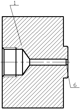
[0025] Such as image 3 , the helix angle of the swirl core 2 is β=27°, and the maximum length can be taken as a lead L...


PUM

PropertyMeasurementUnit
angleaaaaaaaaaa
diameteraaaaaaaaaa
lengthaaaaaaaaaa

Abstract

The invention relates to a hydrodynamic cavitation sludge breaking device. A spiral-flow type jammed cavitation device for breaking excess sludge is characterized by comprising a spiral-flow body, a spiral-flow core, a jammed body and a backpressure cover. The spiral-flow body and the spiral-flow core are matched to form a spiral-flow nozzle. A through hole in the jammed body forms a jammed pipe. The jammed body and the backpressure cover are matched to form a collapse cavity. A backpressure hole is formed in the backpressure cover in the radial direction. After fluid enters the spiral-flow nozzle through the spiral-flow body, flows along a spiral channel to possess the tangential speed and the radial speed, and forms rotating jet flow when being ejected through an outlet end, the rotating jet flow is induced on the upstream of the jammed pipe to generate a large number of cavitation bubbles and an acute shear effect, cavitation bubbles carried by the fluid collapse when the fluid passes through the jammed section on the downstream of the jammed pipe to form jammed cavitation, and when the cavitation bubbles collapse, the mechanical effect of formed micro jet and the like effectively promotes breaking of the excess sludge. Compared with the prior art, the spiral-flow type jammed cavitation device is simple in structure, high in cavitaion strength, strong in mechanical shear force action, high in excess sludge breaking rate and the like.

Description

technical field [0001] The invention relates to the fields of sewage treatment and sludge cracking, and specifically provides a swirl-type clogged cavitator for cracking excess sludge. Background technique [0002] At present, nearly 90% of urban sewage treatment plants in the world use biological treatment processes. Since the biological treatment process was applied to sewage treatment in the early 20th century, it has become the most widely used treatment process in the world, but one of the main weaknesses of this method is that it produces a large amount of residual sludge. The cost of excess sludge treatment is high, accounting for about 25% to 40% of the total operating cost of the sewage treatment plant, and sometimes even as high as 60%. The flocs and bacterial cell walls in the sludge are decomposed slowly in the anaerobic fermentation environment, which hinders the effective degradation of intracellular organic matter, which is the obstacle of the traditional bio...

Claims


Application Information

Patent Timeline
Patent Type & Authority Applications(China)
IPC IPC(8): C02F11/06
CPCC02F11/06C02F2201/002
Inventor 张凤华蒋浩贺照云胡东汪志能
Owner 安徽明亮面业股份有限公司
Why Eureka
Try Eureka