Groove sealed vacuum glass insulation panel and preparation method thereof

A vacuum glass and thermal insulation board technology, applied in glass manufacturing equipment, glass production, glass molding, etc., can solve the problems that thermal insulation materials cannot be used alone for external walls, and the thermal insulation performance of external walls is poor.

Inactive Publication Date: 2016-06-15
戴长虹
View PDF0 Cites 2 Cited by
  • Summary
  • Abstract
  • Description
  • Claims
  • Application Information

AI Technical Summary

Problems solved by technology

[0004] Existing thermal insulation materials cannot be used alone as external walls, and the thermal insulation performance of existing external walls is very poor. If the thermal insulation board is direc

Method used


Image

  • Groove sealed vacuum glass insulation panel and preparation method thereof
  • Groove sealed vacuum glass insulation panel and preparation method thereof
  • Groove sealed vacuum glass insulation panel and preparation method thereof

Examples


Embodiment 1

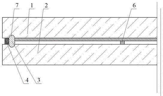
[0069] Embodiment 1: see figure 1 , a vacuum glass insulation panel with an edge sealing groove sealing, two pieces of glass are tempered glass, one of which is low-emissivity glass, and its production method is as follows: firstly, cut the required according to the shape and size of the vacuum glass insulation panel A piece of flat glass and a piece of low-emissivity glass, and set up an edge sealing groove 7 on one of the glasses, and then perform edge grinding, chamfering, cleaning, and drying; secondly, send the two pieces of glass into a tempering furnace for Toughening treatment, then prepare support 6 with polyimide adhesive and glue applicator respectively on two pieces of glass, support 6 is line shape, after two pieces of glass are combined, upper and lower support 6 intersects together; Or use a coating machine to evenly coat one piece of magnesium alloy powder 3 and one piece of polyimide adhesive on the periphery of the two pieces of glass. After merging, it is s...

Embodiment 2

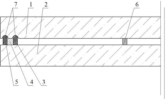
[0071] Example 2: see figure 2 , a planar vacuum glass insulation panel with two edge-sealing grooves and two seals, the difference from Example 8 is that it corresponds to the edge-sealing groove 7 of the upper glass 1, and there is also an edge-sealing groove on the lower glass 2 Groove 7 further strengthens the sealing effect.

Embodiment 3

[0072] Embodiment 3: see image 3 , a vacuum glass insulation panel with two grooves sealed, two pieces of glass are tempered glass, one of which is low-emissivity glass, the production method is as follows: first cut a piece of required size according to the shape and size of the vacuum glass to be produced Flat glass and a piece of low-emissivity glass, and two edge sealing grooves 7 are set on the upper glass 1, and then edge grinding, chamfering, cleaning and drying are carried out; secondly, tempered glass ink and a glue dispenser are used on one of the glasses to prepare The support 6 and the support 6 are point-shaped, and then the two pieces of glass are respectively sent into the tempering furnace for tempering treatment, and the prepared support 6 is also sintered on the glass; the sintered support 6 is mechanically ground again, Make the top in one plane, and round the top edge after grinding to further eliminate the influence of stress; then use a coating machine t...


PUM


Abstract

The present invention discloses a groove vacuum glass insulation panel. The vacuum glass insulation panel includes an upper glass and a lower glass. The peripheries of the upper glass and the lower glass are sealed and connected together through one, two or multiple sealing materials. The sealing materials comprises a glass solder, a metal solder and an adhesive. A sealed vacuum layer is formed between the upper glass and the lower glass. The upper glass and the lower glass are convex glass or flat glass. The convex surface of the convex glass faces towards the outside. The vacuum glass insulation panel preparation method is simple in processes. The prepared vacuum glass insulation panel and tempered vacuum glass insulation panel overcome the deficiencies in the prior art. The preparation method can effectively ensure the tightness and service life of the vacuum glass insulation panel, and can realize mechanized, automatic and mass productions.

Description

technical field [0001] The invention relates to the technical field of glass deep processing, in particular to a vacuum glass insulation panel and a manufacturing method thereof. Background technique [0002] my country's energy resources are relatively short, and long-term energy supply is facing severe challenges. How to solve the energy resource problem is related to the overall economic and social development of our country. With the acceleration of the urbanization process, building energy consumption is getting higher and higher. my country's building energy consumption has accounted for more than 1 / 3 of the energy consumption of the whole society, and it is increasing year by year. The use of thermal insulation building materials is the main way to reduce building energy consumption. One of the means. At present, many materials used for building exterior wall insulation are Class B insulation materials, such as polystyrene, polyurethane, foam rubber and other organi...

Claims


Application Information

Patent Timeline
IPC IPC(8): C03B23/24C03C27/08C03C27/10
CPCY02P40/57
Inventor 戴长虹
Owner 戴长虹
Why Eureka
Try Eureka