Sealed sampling device for gas sample

A technology for sampling device and gas sample, which is applied in the direction of extraction of undisturbed cores, earthwork drilling, etc., can solve the problems of affecting the entry of cores into the inner cylinder and cannot achieve airtight coring, etc., and achieves a wide range of applications, compact device structure, and sealing effect. Good results

Active Publication Date: 2016-06-15
XIAN RES INST OF CHINA COAL TECH& ENG GROUP CORP
View PDF12 Cites 27 Cited by
  • Summary
  • Abstract
  • Description
  • Claims
  • Application Information

AI Technical Summary

Problems solved by technology

[0003] At present, for the airtight coring device, the relevant domestic and foreign documents and patents retrieved are as follows: Chinese patent (201410739874.9) airtight coring device for testing the content of coalbed methane and rock formation gas in ground drilling, which involves airtight coring of gas samples in solid rock cores device, but the airtight valve on the device needs to be pushed by a solid core to close, and the upper airtight valve can only be triggered by a solid core and greater than the length of the inner cylinder. For the sampling length that does not reach the design or there is only gas sample or gas-liquid mixture in the rock sample Under such circumstances, the upper airtight valve cannot be closed, and the purpose of airtight coring cannot be achieved.
[0004] Chinese patent (ZL201010101528.X) an underground coal seam airtight credit-taking device and its use method, which relates to an airtight device for underground coal seam coring. The piston assembly of the device will misoperate the lower closing mechanism under the action of its own weight, which will affect the entry of the core into the inner cylinder.

Method used


Image

  • Sealed sampling device for gas sample
  • Sealed sampling device for gas sample
  • Sealed sampling device for gas sample

Examples


Embodiment Construction

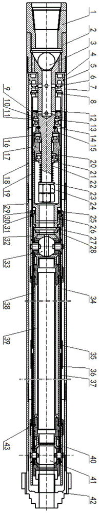
[0036] see figure 1 , shows the gas sample airtight sampling device of the present invention.

[0037] The airtight sampling device for gas samples is arranged in three layers, respectively forming different functions and effects, and is divided into an outer pipe, an inner pipe and a two-layer pipe. The outer pipe includes a connecting mandrel 2, a drill bit 42 and A connecting pipe assembly located between the connecting mandrel 2 and the drill bit 42, the rear end of the connecting mandrel 2 is also provided with a protective joint 1 connected to the driving source, so that the drilling of the drill bit 42 can be realized through the rotation of the driving source and exit.

[0038] Wherein, the connecting pipe assembly comprises a cylinder barrel 7, a first outer tube 18, a second outer tube 29 and a third outer tube 43 which are threaded in sequence, the cylinder barrel 7 is threadedly connected to the connecting mandrel 2, and the first The three outer pipes 43 are thr...


PUM


Abstract

The invention discloses a sealed sampling device for a gas sample. The sealed sampling device comprises an outer pipe, an inner pipe and a double-layer pipe, wherein the outer pipe comprises a connecting mandrel for controlling slurry to enter and exit from a channel, a drill bit and a connecting pipe assembly positioned between the connecting mandrel and the drill bit; the inner pipe at least comprises a connecting sleeve, an upper ball valve, a sealing pipe and a lower ball valve; one end of the connecting sleeve is rotatably connected to the connecting mandrel in a sleeving manner; a core barrel is arranged between the upper ball valve and the lower ball valve, and serves as a storage carrier of a core; the core barrel can be sealed by closing the upper ball valve and the lower ball valve; the tail end of the double-layer pipe is against the connecting mandrel and can move back and forth under the control of the connecting mandrel; and a control element for controlling the opening and closing of the upper ball valve and the lower ball valve is arranged at the front end of the double-layer pipe, so that the upper and lower ball valves are opened or closed by moving the control element forwards or backwards. Therefore, the device is compact in structure, good in seal effect and wide in application range; and during drilling, only the outer pipe rotates and the rest of components do not rotate, thereby ensuring that the core can smoothly enter the core barrel.

Description

technical field [0001] The invention relates to the technical field of drilling tools, in particular to a gas sample airtight sampling device. Background technique [0002] Coring drilling is the most direct method to obtain the target sample and analyze its properties, but after the coring tool obtains the gas or liquid sample in the target hole section, the coring tool needs to seal the rock sample in situ, and then raise the hole for analysis . [0003] At present, for the airtight coring device, the relevant domestic and foreign documents and patents retrieved are as follows: Chinese patent (201410739874.9) airtight coring device for testing the content of coalbed methane and rock formation gas in ground drilling, which involves airtight coring of gas samples in solid rock cores device, but the airtight valve on the device needs to be pushed by a solid core to close, and the upper airtight valve can only be triggered by a solid core and greater than the length of the in...

Claims


Application Information

Patent Timeline
Patent Type & Authority Applications(China)
IPC IPC(8): E21B25/00
CPCE21B25/00
Inventor 殷新胜孙四清张群魏欢欢胡亚张培河张宏钧刘柏根
Owner XIAN RES INST OF CHINA COAL TECH& ENG GROUP CORP
Why Eureka
Try Eureka