Lateral exhaust eccentric steam condensation system and method

A condensing system and eccentric technology, which is applied to steam engine devices, machines/engines, mechanical equipment, etc., can solve the problems of low utilization rate of circulating water, uncertain flow direction, affecting heat transfer effect, etc., to improve condensation heat transfer effect , Improve the efficiency of use, improve the effect of oxygen removal effect

Inactive Publication Date: 2016-06-15
QINGDAO JIENENG HIGH&NEW TECH
View PDF6 Cites 0 Cited by
  • Summary
  • Abstract
  • Description
  • Claims
  • Application Information

AI Technical Summary

Problems solved by technology

[0004] The traditional condensing system has the following technical problems: 1. The traditional condenser is exhausted from the top, that is, the condenser is arranged at the lower part of the steam turbine, so the steam turbine must be arranged at a certain height above the condenser, which not only increases the overhead Civil construction costs, and installation is also very troublesome; 2. The central axis of the heat exchange tube bundle of the traditional condenser system coincides with the central axis of the condenser body, the steam flow range in the heat exchange tube bundle is small, and the flow direction is uncertain, which affects heat transfer Effect, 3. The time and path of circulating water in the traditional condensing system are short, the heat exchange efficiency of the whole system is low, and the utilization rate of circulating water is low

Method used


Image

  • Lateral exhaust eccentric steam condensation system and method
  • Lateral exhaust eccentric steam condensation system and method
  • Lateral exhaust eccentric steam condensation system and method

Examples


Embodiment Construction

[0033] The present invention will be further described below in conjunction with the accompanying drawings and embodiments.

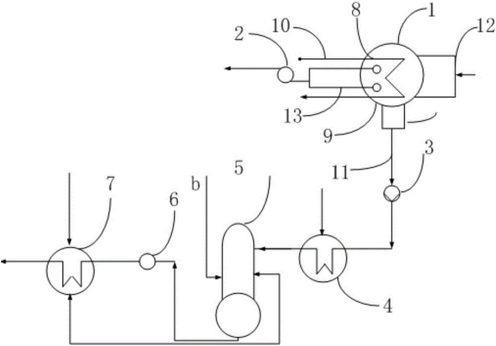
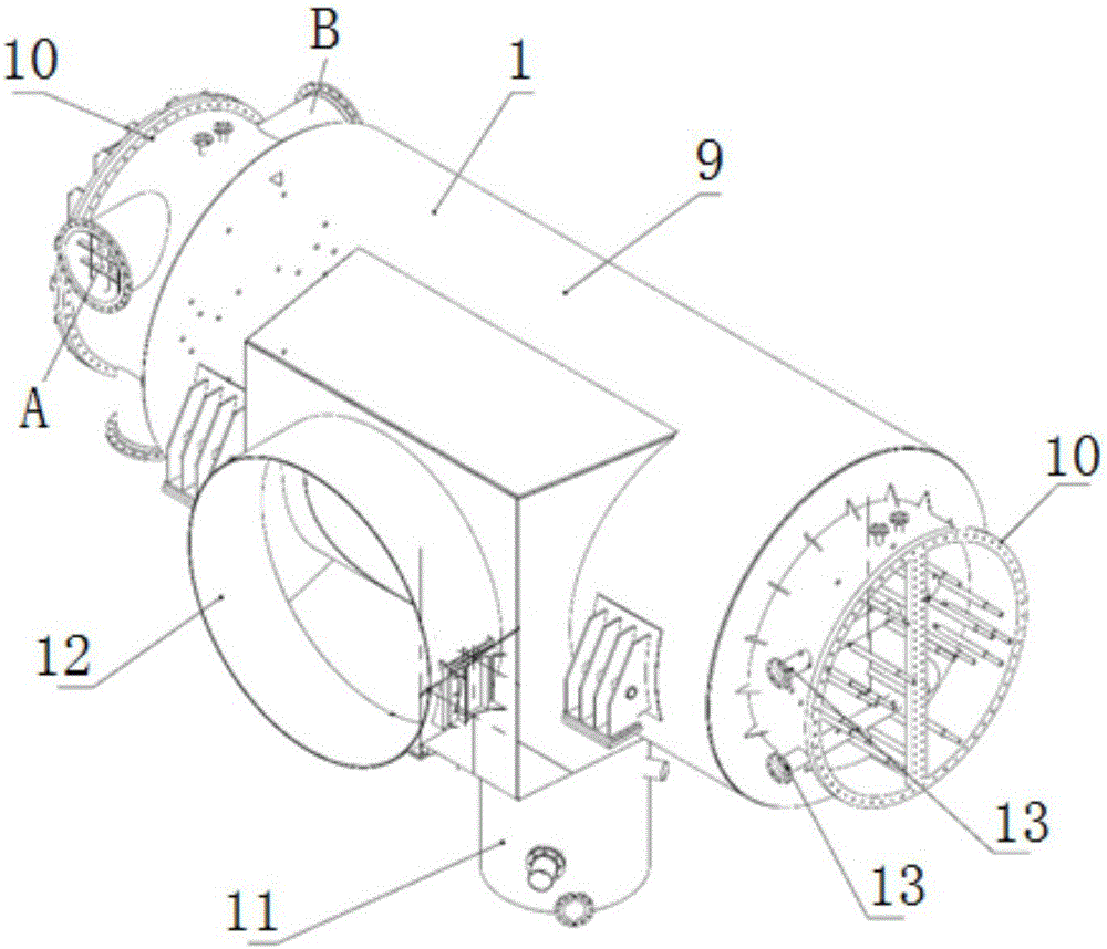
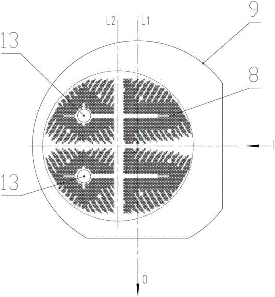
[0034] Such as figure 1 with figure 2 As shown, the side exhaust eccentric condensing system includes a condenser 1, a vacuum pump 2, a condensate pump 3, a low-pressure heater 4 and a deaerator 5, and the condenser 1 passes through the condensate pump 3 and the low-pressure heater 4 connection, the low-pressure heater is connected to the deaerator 5; the condenser includes a condenser body 9, a heat exchange tube bundle 8 arranged inside the condenser body 9, and water chambers arranged on both sides of the condenser body 9 10 and the inlet chamber 12 arranged on the side of the condenser body, the water chamber 10 is connected to the exhaust pipe, the center line of the heat exchange tube bank 8 is parallel to the central axis of the condenser body 9, and the heat exchange tube bank 8 An air extraction port 13 is arranged, and the air extraction po...


PUM


Abstract

The invention discloses a lateral exhaust eccentric steam condensation system and method. The lateral exhaust eccentric steam condensation system comprises a steam condenser, a vacuum pump, a condensate pump, a low-pressure heater and a deaerator, wherein the steam condenser is connected with the low-pressure heater through the condensate pump; the low-pressure heater is connected with the deaerator; the steam condenser comprises a steam condenser body, a heat exchange tube bundle arranged in the steam condenser body, a water chamber arranged at two sides of the steam condenser body and an air inlet chamber arranged at the side of the steam condenser body, wherein the water chamber is connected with an exhaust duct; the central axis of the heat exchange tube bundle is parallel to the central axis of the steam condenser body; and an air extraction hole is arranged in the heat exchange tube bundle and is connected with the vacuum pump. The lateral exhaust eccentric steam condensation system has the beneficial effects that the air inlet chamber of the steam condenser is arranged at the side of the steam condenser body, so that the height of a steam turbine is reduced; and the heat exchange tube bundle is eccentrically arranged in the steam condenser body, so that the flowing uniformity of steam in the heat exchange tube bundle and the utilization efficiency of circulating water are increased.

Description

technical field [0001] The invention relates to the technical field of condensation water systems, in particular to a side exhaust eccentric steam condensation system and method. Background technique [0002] At present, the condensing system is one of the important sub-systems in the thermal system of a power plant. The condensing system provides a cold source for the entire thermal system, and plays the role of preheating and deoxygenating the boiler feed water, reducing the heat transfer of the entire thermal system. The end difference improves the exergy efficiency, and its efficiency is directly related to the power generation efficiency of the whole field thermal system. [0003] Among them, the condenser condenses the saturated steam of the steam turbine into saturated water through the heat exchange of the cooling water partition wall, so that the thermal system can recycle the condensed water, and at the same time, the non-condensable gas leaked into the thermal sys...

Claims


Application Information

Patent Timeline
Patent Type & Authority Applications(China)
IPC IPC(8): F01K9/00
CPCF01K9/00
Inventor 刘锡荣韩振宇战福帅刘洪顺
Owner QINGDAO JIENENG HIGH&NEW TECH
Why Eureka
Try Eureka