
Automatic clutch device with constant-power flow direction

An automatic clutch, constant power technology, applied in one-way clutches, clutches, mechanical equipment, etc., can solve the problem of idling in the direction of reverse power transmission, and achieve the effects of large economic application value, small size and simple structure

Active Publication Date: 2016-06-15
QINGAN GRP
View PDF7 Cites 1 Cited by
  • Summary
  • Abstract
  • Description
  • Claims
  • Application Information

AI Technical Summary

Problems solved by technology

[0002] At present, automatic clutch devices with fixed power flow generally use multi-wedge or ratchet-pawl structures with specific input and output ends. Break away from the braking position, the clutch main shaft works normally and transmits power; but when the wedge enters the braking position in the reverse direction of power transmission, the main shaft keeps braking, and the idling when the power transmission direction is reversed cannot be realized (that is, one end is dragged and rotated, and the other end is held Do not move)

Method used


Image

  • Automatic clutch device with constant-power flow direction

Examples


Embodiment Construction

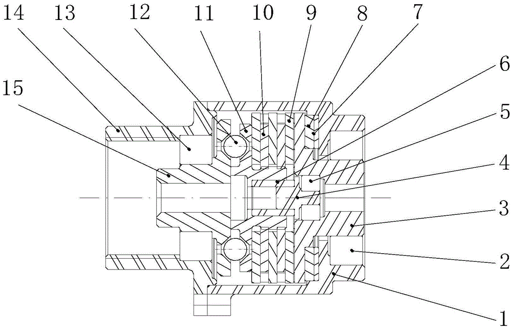
[0010] in figure 1 In the example shown, the entire structure is contained between the left housing 14 and the right housing 1, and power is only allowed to be transmitted from the input shaft 15 to the output shaft 3. When the torque and speed (whether clockwise or counterclockwise) act on the output shaft 3, the output shaft and the dynamic friction plate 10 are dragged to rotate, but due to the action on the top wave spring 6, there is no space between the dynamic friction plate 10 and the static friction plate 9 Positive pressure cannot transmit torque, that is, the static friction plate 9 and the input shaft 15 remain stationary, and the output shaft remains idling under drag; when the input shaft 15 is actively running (regardless of clockwise or counterclockwise), the ring on the input shaft 15 The inclined surface will push the steel ball 12 in the axial direction to move in a small range. After overcoming the resistance of the top wave spring 6 (only need 0.1~0.2mm str...


PUM


Abstract

The invention relates to an automatic clutch device with a constant-power flow direction. The automatic clutch device is used for a manual operation mechanism of an airplane cabin door and a manual manipulating device of a winch. At present, according to an automatic clutch device with the constant-power flow direction, a multi-wedge-block-pawl structure or a ratchet-wheel-pawl structure is commonly used, and a specific input end and a specific output end are included; when power is transmitted in the direction from the input end to the output end, wedge blocks are separated from a brake device, and a clutch spindle normally works to transmit power; but in the reverse-power transmission direction, the wedge blocks enter the brake position, the spindle keeps braking, and idling in the reverse-power transmission direction cannot be achieved; and the automatic clutch device has the beneficial effects of being simple in structure, light and small in size. The condition that a manual operation mechanism is dragged to rotate is avoided, non-work wear of most parts in the manual operation mechanism is reduced, the service life of the parts is prolonged, and economic benefits are obvious. Therefore, the automatic clutch device has the great economic application value.

Description

Technical field [0001] The invention relates to a constant power flow direction automatic clutch device, which is used for an operating mechanism of an aircraft door and an operating device of a winch. Background technique [0002] At present, automatic clutch devices with fixed power flow generally use multi-wedge or ratchet-pawl structure, with specific input and output ends. When transmitting power from input to output (that is, in the positive direction of power transmission), the wedge is used Disengage from the braking position, the main shaft of the clutch works normally to transmit power; but when the direction of power transmission is reversed, the wedge enters the braking position, and the main shaft keeps braking. Idling in the reverse power transmission direction cannot be achieved (that is, one end is dragged and the other is held Do not move). Summary of the invention [0003] The technical problem to be solved by the present invention is to realize one-way power tr...

Claims


Application Information

Patent Timeline
Patent Type & Authority Applications(China)
IPC IPC(8): F16D41/064
CPCF16D41/064
Inventor 宣源鹏李建仁刘冬平杜秀军
Owner QINGAN GRP
Learn More