Low-dew-point positive pressure air supply system and dehumidification method for high-voltage cabinet

A technology of air supply system and high-voltage cabinet, which is applied in the direction of air conditioning system, heating method, space heating and ventilation, etc. It can solve the problems of reduced insulation strength, high humidity of switch cabinets, and flashover of insulating parts, so as to reduce air humidity , reduce moisture content, reduce the effect of dew point temperature

Inactive Publication Date: 2016-06-15
STATE GRID JIANGSU ELECTRIC POWER CO LTD MAINTENANCE BRANCH +1
View PDF5 Cites 17 Cited by
  • Summary
  • Abstract
  • Description
  • Claims
  • Application Information

AI Technical Summary

Problems solved by technology

[0002] At this stage, there are many ways to dehumidify high-voltage electrical cabinets. There are dehumidifiers installed in the high-voltage room, traditional heating and dehumidification devices in the cabinet, and semiconductor dehumidifiers, but the effect is not obvious, because simply relying on the external environment of the high-voltage cabinet Install dehumidification in the high-voltage chamber, or place a heater in the high-voltage cabinet, or use special thermoelectric semiconductor materials to manufacture semiconductor refrigeration devices for dehumidification according to the Peltier effect. Facts have proved that the above methods cannot effectively prevent humidity in the high-voltage cabinet. overgas, forming condensation
[0003] To solve...

Method used


Image

  • Low-dew-point positive pressure air supply system and dehumidification method for high-voltage cabinet
  • Low-dew-point positive pressure air supply system and dehumidification method for high-voltage cabinet
  • Low-dew-point positive pressure air supply system and dehumidification method for high-voltage cabinet

Examples


Embodiment Construction

[0029] In order to make the technical means, creative features, goals and effects achieved by the present invention easy to understand, the present invention will be further described below in conjunction with specific embodiments.

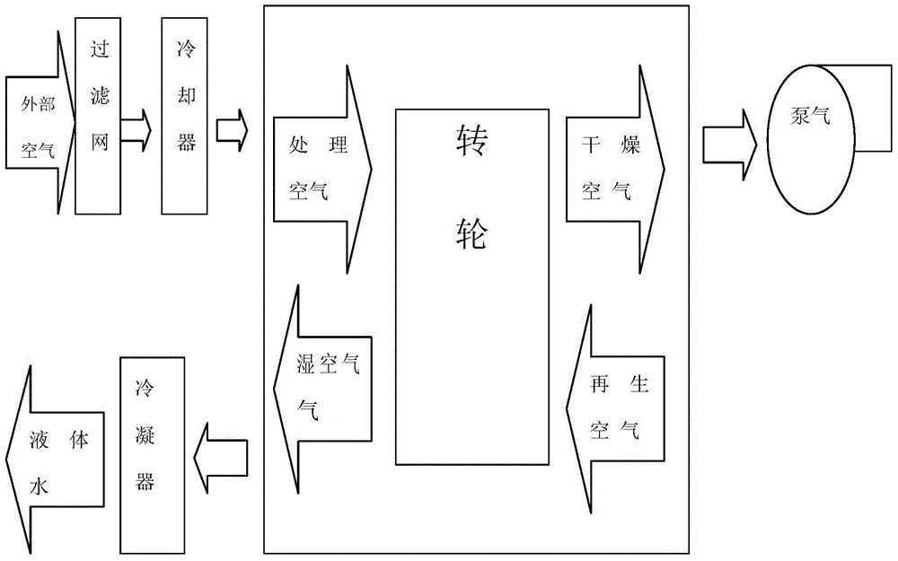
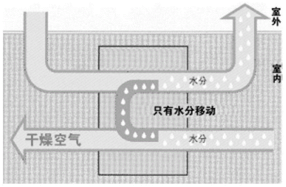
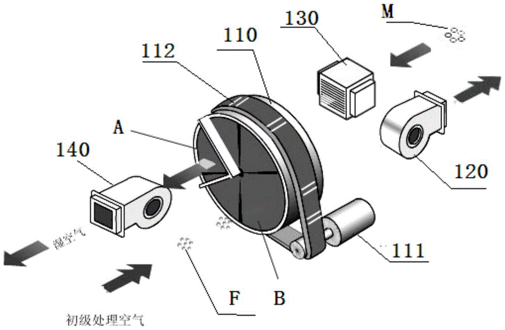
[0030] see Figure 1 to Figure 3 , the high pressure cabinet low dew point positive pressure air supply system of this embodiment, which includes a filter installed in the ventilation duct and a rotary dehumidifier connected to the filter through the ventilation duct and used to cool the temperature of the external air delivered from the outside The cooler; the ventilation pipe is used for high-pressure indoor and outdoor communication, and the intake end of the rotary dehumidifier is connected to the cooler and filter through the ventilation pipe, and the cooling is started when the external air temperature is higher than 18-20°C After the external air is filtered by the filter part, it is then processed by a compression cooler to reduce the air ...


PUM


Abstract

The invention relates to a low dew point positive pressure air supply system for a high-pressure cabinet and a dehumidification method thereof. The cooler for the temperature of the external air delivered from the outside; when the temperature of the external air is higher than 18-20°C, the cooler is started, and the external air is filtered by the filter part, and then processed by a compression cooler to reduce the air temperature to 14°C -16°C, and then sent to the rotary dehumidifier for dehumidification; the rotary dehumidifier will continuously absorb the water molecules in the high-pressure cabinet and convert it into humid air, discharge it out of the high-pressure cabinet in the high-pressure chamber, and transport the dry air after heating and dehumidification To the high-voltage cabinet to achieve the purpose of continuous dehumidification of the high-voltage cabinet. The present invention completely reduces the moisture content of the air in the cabinet, thereby reducing the air humidity and dew point temperature in the cabinet, thereby avoiding the occurrence of condensation, ensuring that the air pressure in the cabinet is positive relative to the outside of the cabinet and that there is no dead angle in the high-voltage cabinet.

Description

technical field [0001] The invention relates to the field of a dehumidification method for a high-voltage electrical cabinet and an exhaust system thereof, in particular to a low dew point positive pressure air supply system for a high-voltage cabinet and a dehumidification method thereof. Background technique [0002] At this stage, there are many ways to dehumidify high-voltage electrical cabinets. There are dehumidifiers installed in the high-voltage room, traditional heating and dehumidification devices in the cabinet, and semiconductor dehumidifiers, but the effect is not obvious, because simply relying on the external environment of the high-voltage cabinet Install dehumidification in the high-voltage chamber, or place a heater in the high-voltage cabinet, or use special thermoelectric semiconductor materials to manufacture semiconductor refrigeration devices for dehumidification according to the Peltier effect. Facts have proved that the above methods cannot effectivel...

Claims


Application Information

Patent Timeline
IPC IPC(8): F24F3/14H02B1/56
CPCF24F3/14F24F2003/1458H02B1/565
Inventor 苏和陆剑云蒋树风张云飞马益峰黄晓伟刘晓星
Owner STATE GRID JIANGSU ELECTRIC POWER CO LTD MAINTENANCE BRANCH
Why Eureka
Try Eureka