A Texture-Based Depth Image Boundary Correction Method

A technology of depth image and texture image, applied in image analysis, image enhancement, image data processing, etc., can solve the problems of unsatisfactory filtering effect in boundary area and fluctuation of boundary depth value, so as to improve reliability and ensure robustness Effect

Active Publication Date: 2019-06-28
SHENZHEN INST OF FUTURE MEDIA TECH +1
View PDF5 Cites 0 Cited by
  • Summary
  • Abstract
  • Description
  • Claims
  • Application Information

AI Technical Summary

Problems solved by technology

There are two representative methods: preprocessing the depth image with a bilateral filter, then dividing the depth image into non-boundary areas and boundary areas in the spatial domain, and enhancing the depth information with a special weighting method for the boundary area, which reduces the The depth image is noisy in the object boundary area, but due to the lack of time-domain stability constraints, there are still large fluctuations in the boundary depth values ​​of adjacent frames; use the texture-weighted average of the depth information of multiple frames in the time domain to improve the depth Image stability, the method of joint bilateral filtering of the current frame depth image from the time domain and the space domain greatly improves the temporal consistency of the depth image, and the continuity of the depth value of the smooth surface is significantly improved, but due to the neglect of the affected Noise affects the processing of the object boundary greatly, the filtering effect of the boundary area is not ideal, and the boundary dislocation needs to be suppressed

Method used


Image

  • A Texture-Based Depth Image Boundary Correction Method
  • A Texture-Based Depth Image Boundary Correction Method
  • A Texture-Based Depth Image Boundary Correction Method

Examples


Embodiment Construction

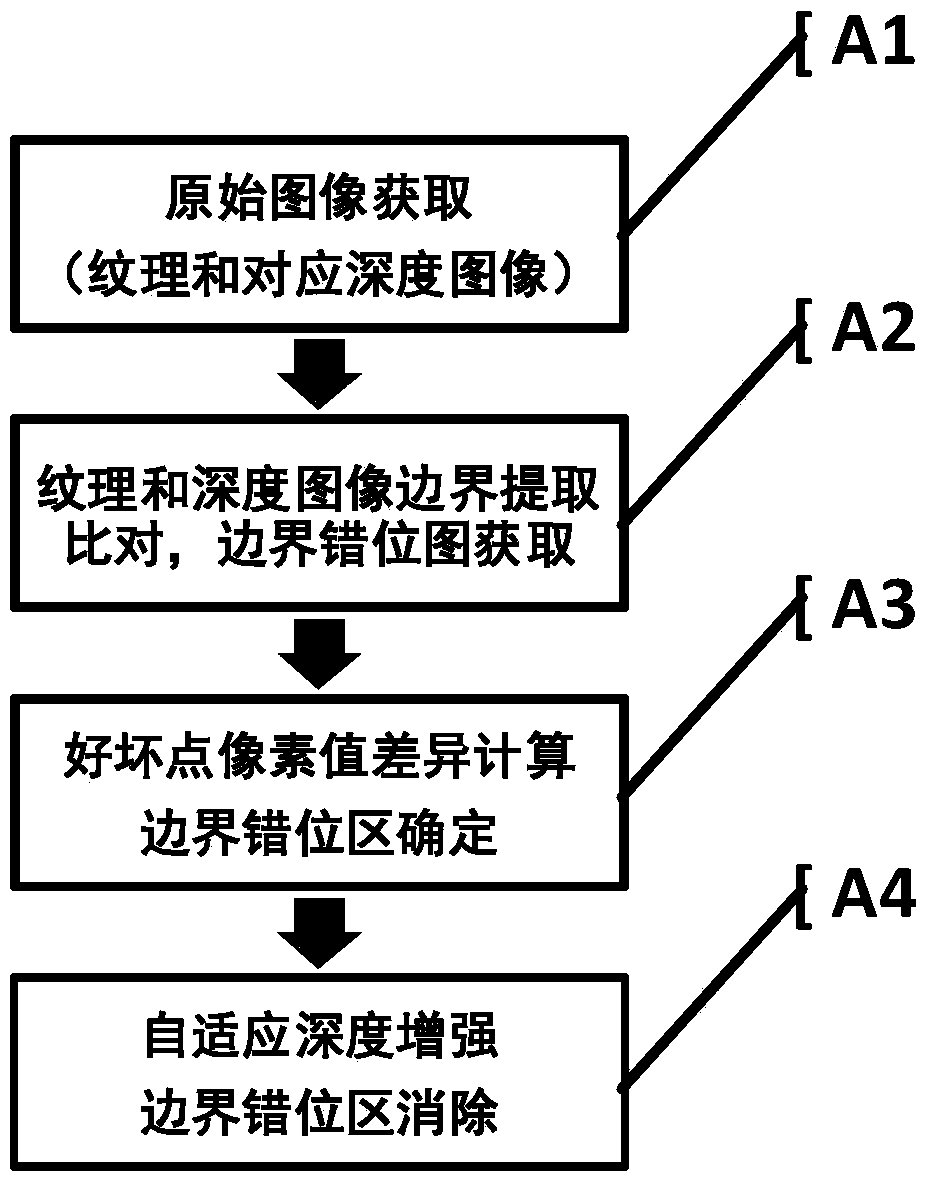
[0010] In order to obtain a high-quality depth image with clear and smooth object boundaries, complete shape, and accurate position, it is necessary to integrate the advantages of various improved depth image methods for the boundary area of ​​the depth image and learn from each other. The idea of ​​the embodiment of the present invention is mainly based on the two main problems of jitter and misalignment in the boundary area of ​​the depth image. With the help of the stable and accurate corresponding texture image boundary, the depth enhancement process is performed on the boundary area to improve the accuracy of the air space and the stability of the time domain. The purpose of comprehensively suppressing the boundary errors in the depth images collected by low-end depth sensors is to facilitate the further integration of depth information into other applications.

[0011] In this embodiment, by extracting the boundary of each frame of the texture image and comparing it with ...


PUM


Abstract

The present invention relates to a texture-based depth boundary correction method. The method comprises the steps of A1, inputting a texture image and a corresponding depth image, wherein the images are acquired by a depth sensor (such as a Kinect); A2, extracting the boundary of the texture image and the boundary of the depth image, and acquiring a depth boundary dislocation figure with the boundary of the texture image as the reference; A3, calculating the pixel value difference between an accurate depth point (sweet spot) and an error depth point (dead point) and determining a boundary dislocation area; A4, according to the distribution characteristics of the boundary dislocation area, adaptively determining the side length of a square window for depth enhancement processing, correcting the depth of the dead point in the window, eliminating the boundary dislocation area. According to the invention, the accuracy and the time-domain stability of the boundary of the depth image, acquired by the Kinect and other low-end depth sensors, are significantly improved. The method is applied to the fields of three-dimensional reconstruction, free viewpoint video coding and the like, and can effectively improve the scene three-dimensional reconstruction quality and the coding efficiency.

Description

technical field [0001] The invention relates to the fields of computer vision and digital image processing, in particular to a texture-based depth image boundary correction method. Background technique [0002] Depth images are often used in many fields such as 3D reconstruction and free viewpoint coding. Existing depth information collection is often based on some complex and expensive sensors, such as structured light cameras or laser range finders. The depth images collected based on these devices are not only disturbed by various noises, but also the low resolution greatly limits the development of other research applications based on depth images. Low-end depth sensors represented by Kinect are widely used in research because they are cheap and active sensors that can quickly acquire scene depth and texture information. However, because the low-end depth sensor mainly obtains the scene depth image by emitting structured light and receiving its reflected light, it is s...

Claims


Application Information

Patent Timeline
Patent Type & Authority Patents(China)
IPC IPC(8): G06T7/13
CPCG06T2207/10028
Inventor 金欣许娅彤张新戴琼海
Owner SHENZHEN INST OF FUTURE MEDIA TECH
Why Eureka
Try Eureka