Structure for modular motor stator and end part overlapping fractional slot windings of modular motor stator

A motor stator and winding structure technology, applied in the shape/style/structure of winding conductors, electric components, magnetic circuit shape/style/structure, etc., can solve the unfavorable large motor production, transportation and maintenance, non-working harmonic content Many, unable to modularize the motor and other problems, to achieve the effect of strong fault tolerance, small mutual inductance between phases, and small cogging torque

Active Publication Date: 2016-06-15
SOUTHEAST UNIV
View PDF5 Cites 29 Cited by
  • Summary
  • Abstract
  • Description
  • Claims
  • Application Information

AI Technical Summary

Problems solved by technology

[0003] However, the non-working harmonic content and high amplitude of the fractional slot concentrated winding MMF are likely to cause additional torque ripple and rotor loss, which makes the heat dissipation, vibration and The noise problem is particularly prominent
Distributed integer slot windings and non-concentrated fractional slot windings have less harmonic components, but the end windings at all positions on the stator circumference of the two overlap, which makes it impossible to modularize the motor, which is not conducive to the production, transportation and maintenance of large motors

Method used


Image

  • Structure for modular motor stator and end part overlapping fractional slot windings of modular motor stator
  • Structure for modular motor stator and end part overlapping fractional slot windings of modular motor stator
  • Structure for modular motor stator and end part overlapping fractional slot windings of modular motor stator

Examples


Embodiment Construction

[0021] The working mechanism and advantages of the present invention will be described in more detail below through a specific embodiment and related drawings.

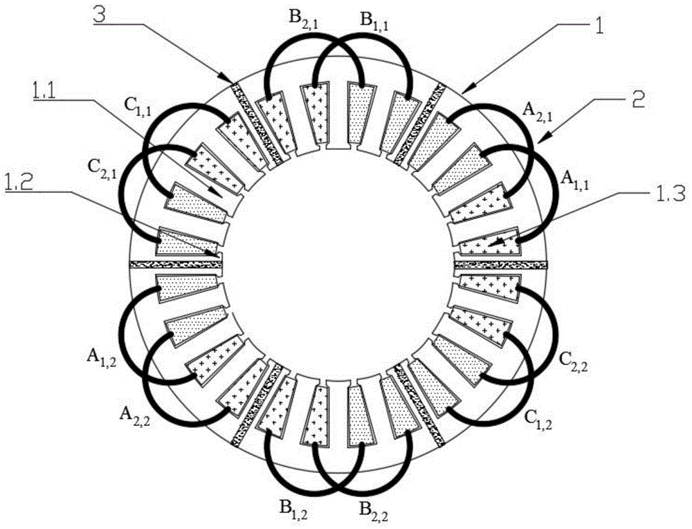
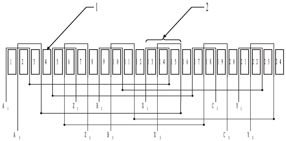
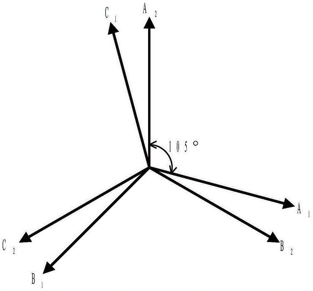
[0022] Such as figure 1 Shown is a schematic diagram of a 24-slot 7-pair permanent magnet synchronous motor stator and its end windings using a modular motor stator and its end overlapping fractional slot winding structure. The stator 1 includes armature teeth 1.1 , fault-tolerant teeth 1.2 , stator slots 1.3 and a non-magnetic isolation layer 3 . Stator 1 is wound with end-overlapping fractional slot winding 2, which is composed of two sets of three-phase symmetrical AC windings as a whole. Each stator slot 1.3 contains only one coil edge, and the entire winding 2 has 12 coils in total. The distribution of overlapping parts on the circumference of the stator is discontinuous, and the stator can be cut into several modules along the junction of the overlapping areas of two adjacent end windings. The motor has 6 stat...


PUM


Abstract

The invention provides a structure for a modular motor stator and end part overlapping fractional slot windings of the modular motor stator. The number of stator slots and the number of winding pole pairs are set to be 2Z and p respectively, wherein the stator slots are evenly distributed on the circumference; the stator comprises two sets of three-phase symmetric AC windings; the windings are evolved from traditional single-layer concentrated fractional slot windings; the arrangement of each set of windings is the same as that of the traditional single-layer concentrated fractional slot windings with Z slots and p pole pairs; the staggered angle of two sets of windings is one half of a coil span mechanically; overlapping regions at the end parts of the windings are distributed on the circumference of the stator at intervals; and modularization can be achieved by cutting the stator in the non-overlapping regions at the end parts of the windings. The structure can greatly reduce the non-working tooth harmonic content in magnetomotive force of the traditional concentrated fractional slot windings, so that the motor loss can be reduced; torque pulsation is stabilized; the noise is reduced; meanwhile, the structure has the advantage that the motor stator with the concentrated fractional slot windings can be modularized; manufacturing, transportation and assembly of a large motor are facilitated; the interphase mutual inductance is small; and improvement of the fault-tolerant capability of the motor is facilitated.

Description

technical field [0001] The invention relates to a modular motor stator and its winding structure with overlapping fractional slots at its ends, belonging to the technical field of motors. Background technique [0002] Motors with fractional slot concentrated windings are being more and more widely used in various fields. Compared with traditional distributed winding motors, fractional slot concentrated winding motors have small torque ripple, high sine degree of back EMF waveform, and strong fault tolerance. High torque density, low cogging torque and other advantages. In addition, since the coil ends of the concentrated winding with fractional slots do not overlap, the stator of this type of motor can be modularized. Modularization can reduce the difficulty of manufacturing the motor, improve the slot fullness rate, and reduce the cost of large-scale direct-drive wind power generation and ship propulsion. Assembly and maintenance costs such as large motor applications. ...

Claims


Application Information

Patent Timeline
Patent Type & Authority Applications(China)
IPC IPC(8): H02K1/16H02K3/28
CPCH02K1/165H02K3/28
Inventor 林鹤云王克羿阳辉
Owner SOUTHEAST UNIV
Why Eureka
Try Eureka